Bryant LOW-BOY 367AAN User Manual
Page 5
When ducts are used to supply air, they must be of the same cross
sectional area as free area of openings to which they connect.
The minimum dimension of rectangular air ducts must not be less
than 3 in.
DUCT WORK RECOMMENDATIONS
WARNING:
When supply ducts carry air circulated by
furnace to areas outside spaces containing furnace, return
air MUST also be handled by a duct sealed to furnace
casing and terminating outside space containing furnace.
Incorrect duct work termination and sealing will create a
hazardous condition which could lead to bodily harm.
CAUTION:
Return-air grilles and warm air registers
MUST NOT be obstructed.
The proper sizing of warm air ducts is necessary to ensure
satisfactory furnace operation. Duct work should be in accordance
with the latest editions of NFPA-90A (Installation of Air Condi-
tioning and Ventilating Systems) and NFPA-90B (Warm Air
Heating and Air Conditioning Systems) or Canadian equivalent.
The supply duct work should be attached to flanged front opening
provided at discharge end of furnace. The return-air duct work
should be attached to flanged rear opening of furnace. See Fig. 2
for dimensions of these openings.
NOTE:
The back (blower access opening) should not be used for
return air.
The following recommendations should be followed when install-
ing duct work:
1. Install locking-type dampers in all branches of individual
ducts to balance out system. Dampers should be adjusted to
impose proper static at outlet of furnace.
2. A flexible duct connector of noncombustible material
should be installed at unit on both supply- and return-air
systems. In applications where extremely quiet operation is
necessary, the first 10 ft (if possible) of supply and return
ducts should be internally lined with acoustical material.
3. In cases where return-air grille is located close to fan inlet,
there should be at least one 90° air turn between fan inlet
and grille. Further reduction in sound level can be accom-
plished by installing acoustical air turning vanes or lining
duct as described in item 2 above.
4. When a single air grille is used, duct between grille and
furnace must be the same size as return opening in furnace.
VENTING
Venting of furnace should be to the outside and in accordance with
local codes or requirements of local utility.
OIL-FIRED APPLIANCES SHALL BE CONNECTED TO
FLUES HAVING SUFFICIENT DRAFT AT ALL TIMES TO
ENSURE SAFE AND PROPER OPERATION OF APPLIANCE.
For additional venting information, refer to ANSI/NFPA 211
Chimney, Fireplaces, Vents, and Solid Fuel Burning Appliances
and/or CSA B139 Installation Code.
This furnace is certified for use with Type "L" vent (maximum flue
gas temperature 575°F).
I.
VENT SYSTEM INSPECTION
Before furnace is installed, it is highly recommended that any
existing vent system be completely inspected.
For any chimney or vent, this should include the following:
1. Inspection for any deterioration in chimney or vent. If
deterioration is discovered, chimney must be repaired or
vent must be replaced.
2. Inspection to ascertain that vent system is clear and free of
obstructions. Any blockage must be cleared before install-
ing furnace.
3. Cleaning chimney or vent if previously used for venting a
solid fuel burning appliance or fireplace.
4. Confirming that all unused chimney or vent connections are
properly sealed.
5. Verification that chimney is properly lined and sized per the
applicable codes. (Refer to list of codes in Safety Consid-
erations section.)
II.
MASONRY CHIMNEYS
This furnace can be vented into an existing masonry chimney. This
furnace must not be vented into a chimney servicing a solid fuel
burning appliance. Before venting furnace into a chimney, the
chimney MUST be checked for deterioration and repaired if
necessary. The chimney must be properly lined and sized per local
or national codes.
If furnace is vented into a common chimney, the chimney must be
of sufficient area to accommodate the total flue products of all
appliances vented into chimney.
The following requirements are provided for a safe venting
system:
1. Be sure that chimney flue is clear of any dirt or debris.
2. Be sure that chimney is not servicing an open fireplace.
3. Never reduce pipe size below the outlet size of furnace.
(See Fig. 2.)
4. All pipe should be supported using proper clamps and/or
straps. These supports should be at least every 4 ft.
5. All horizontal runs of pipe should have at least 1/4 in. per
ft of upward slope.
6. All runs of pipe should be as short as possible with as few
turns as possible.
7. Seams should be tightly joined and checked for leaks.
8. The flue pipe must not extend into chimney but be flush
with inside wall.
9. The chimney must extend 3 ft above highest point where it
passes through the roof of a building and at least 2 ft higher
than any portion of a building within a horizontal distance
of 10 ft. It shall also be extended at least 5 ft above highest
connected equipment flue collar.
10. Check local codes for any variance.
III.
FACTORY-BUILT CHIMNEYS
Listed factory-built chimneys may be used. Refer to chimney
manufacturer’s instructions for proper installation.
OIL BURNER
This furnace is supplied with a high-pressure atomizing retention
head-type burner (for use with grade 1 or 2 fuel oil). The mounting
flange is fixed to burner air tube and no adjustment is required for
insertion length.
For Example:
→
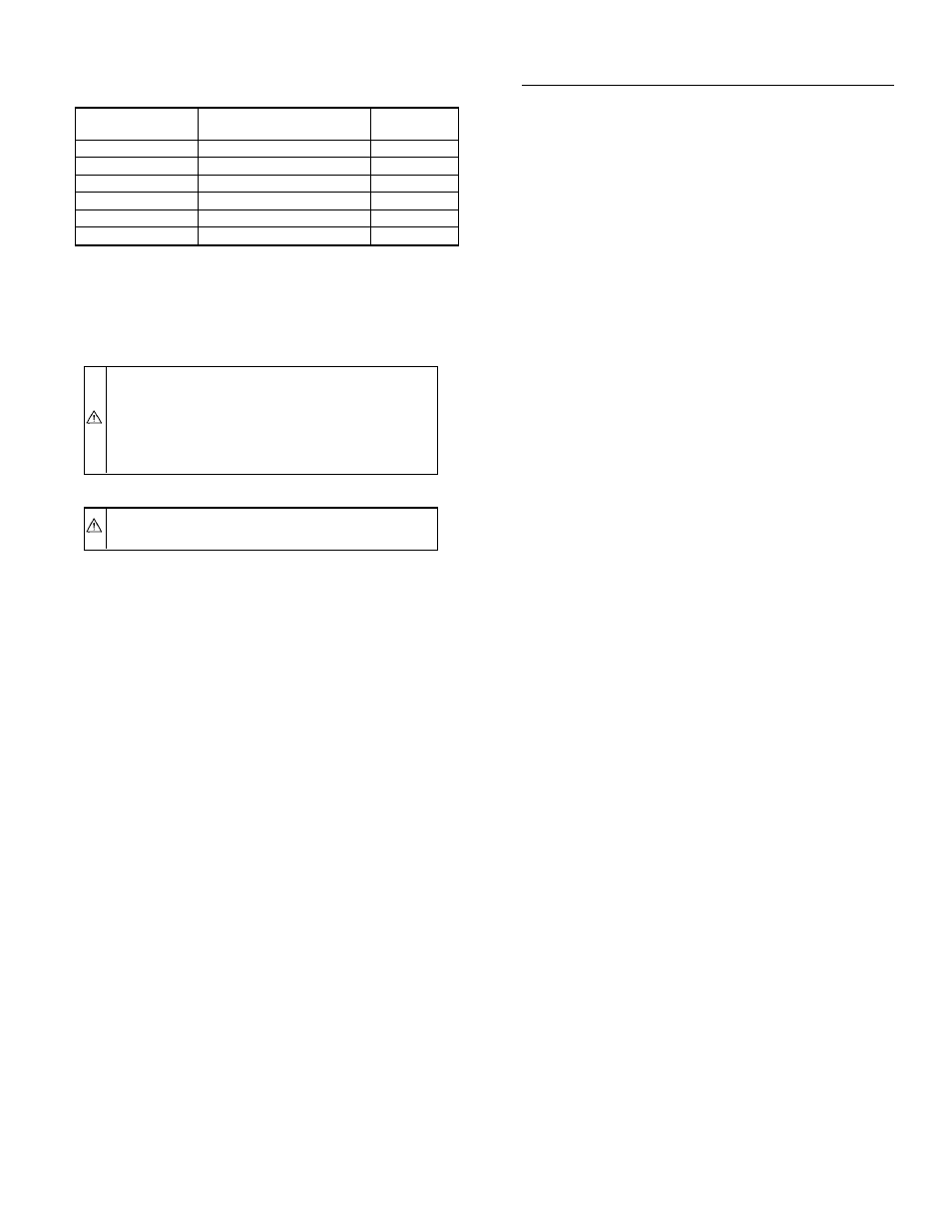
COMBUSTION AIR FROM OUTDOORS THROUGH
HORIZONTAL DUCTS
367AAN FURNACE
INPUT BTUH
FREE AREA PER OPENING
(SQ IN.)
ROUND PIPE
(IN. DIAM)
70,000
35.0
7
91,000
45.5
8
105,000
52.5
9
119,000
59.5
9
140,000
70.0
10
154,000
77.0
10
—5—