Table 2 — electrical data, Table 3 — heat anticipator settings, Fig. 12 — field control thermostat wiring – Bryant DURAPAC PLUS SERIES 542J User Manual
Page 9: Fig. 13 — optional non-fused disconnect wiring
—
9
—
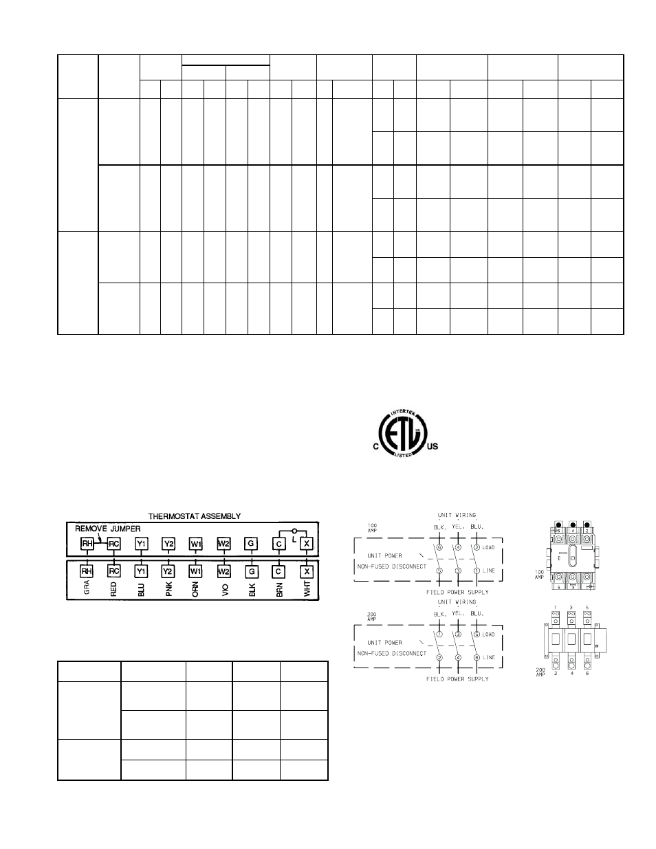
Table 2 — Electrical Data
LEGEND
*Heater capacity (kW) is based on heater voltage of 208 v, 240 v, and
480 v. If power distribution voltage to unit varies from rated heater volt-
age, heater kW will vary accordingly.
†Fuse or HACR circuit breaker. This is the maximum size permissible;
smaller fuse size may be used where conditions permit.
NOTES:
1. In compliance with NEC requirements for multimotor and combina-
tion load equipment (refer to NEC Articles 430 and 440), the over-
current protective device for the unit shall be fuse or HACR
breaker. The Canadian units may be fuse or circuit breaker.
2. MCA calculation for units with electric heaters over 50 kW = (1.25 x
IFM amps) + (1.00 x heater FLA).
Table 3 — Heat Anticipator Settings
UNIT
542J
VOLTAGE
(3 Ph,
60 Hz)
VOLTAGE
RANGE
COMPRESSOR
OUTDOOR
FAN
MOTOR
INDOOR FAN
MOTOR
POWER
EXHAUST
ELECTRIC HEAT*
POWER SUPPLY
DISCONNECT
SIZING
No. 1
No. 2
Min
Max RLA LRA RLA LRA
Qty
FLA
(ea)
Hp
FLA
FLA
LRA
FLA
kW
MCA
MOCP†
RLA
LRA
150
208/230
187
253
39.7
228
—
—
3
1.7
3.7
10.5/10.5
—
—
—/—
—/—
65/ 65
100/100
64/ 64
387/387
39/ 45
14/19
114/122
125/150
64/ 64
72/ 82
26/34
155/168
175/175
94/107
117/135
42/56
211/200
225/225 147/167
4.6
18.8
—/—
—/—
70/ 70
100/100
69/ 69
406/406
39/ 45
14/19
119/126
125/150
69/ 69
72/ 82
26/34
159/173
175/175 100/112
117/135
42/56
216/205
225/225 152/173
460
414
508
19.9
114
—
—
3
0.8
3.7
4.8
—
—
—
—
32
50
31
189
18
15
54
60
31
39
32
81
90
50
66
55
98
110
82
2.3
6.0
—
—
34
50
34
195
18
15
57
70
34
39
32
83
90
53
66
55
100
110
84
180
208/230
187
253
28.2
160
28.2
160
3
1.7
5
15.8/15.8
—
—
—/—
—/—
84/ 84
110/110
89/ 89
499/485
72/ 82
26/34
174/187
175/200 101/112
117/135
42/56
231/219
250/225 153/173
4.6
18.8
—/—
—/—
89/ 89
110/110
94/ 94
518/504
72/ 82
26/34
179/191
200/200 106/118
117/135
42/56
235/224
250/225 158/179
460
414
508
14.1
80
14.1
80
3
0.8
5
7.9
—
—
—
—
42
50
44
238
39
32
91
100
54
66
55
108
110
85
2.3
6.0
—
—
44
50
47
244
39
32
93
100
57
66
55
110
125
88
FLA
— Full Load Amps
HACR — Heating, Air Conditioning and Refrigeration
LRA
— Locked Rotor Amps
MCA
— Minimum Circuit Amps
MOCP — Maximum Overcurrent Protection
NEC
— National Electrical Code
RLA
— Rated Load Amps
UNIT 542J
UNIT
VOLTAGE
HEATER
kW
STAGE 1
STAGE 2
150
208/230-3-60
14/19
.40
—
26/34
.40
.40
42/56
.66
.40
460
15
.40
—
32
.40
.40
55
.40
.66
180
208/230
26/34
.40
.66
42/56
.66
.40
460
32
.40
.40
55
.40
.66
Fig. 12 — Field Control Thermostat Wiring
5L3 3L2 1L1 LINE
6T3 4T2 2T1 LOAD
NOTE: The disconnect takes the place of TB-1 as shown on the unit
wiring diagram label and the component arrangement label.
Fig. 13 — Optional Non-Fused Disconnect Wiring