Bryant DURAPAC PLUS SERIES 542J User Manual
Page 14
—
14
—
Outdoor Enthalpy Changeover
For enthalpy control, accessory enthalpy sensor (part num-
ber HH57AC078) is required. Replace the standard outdoor
dry bulb temperature sensor with the accessory enthalpy
sensor in the same mounting location. See Fig. 20. When the
outdoor air enthalpy rises above the outdoor enthalpy
changeover set point, the outdoor-air damper moves to its
minimum position. The outdoor enthalpy changeover set
point is set with the outdoor enthalpy set point potentiome-
ter on the EconoMi$erIV controller. The set points are A, B,
C, and D. See Fig. 26. The factory-installed 620-ohm jumper
must be in place across terminals SR and SR+ on the
EconoMi$erIV controller. See Fig. 23 and 27.
Differential Enthalpy Control
For differential enthalpy control, the EconoMi$erIV controller
uses two enthalpy sensors (HH57AC078 and
CRENTDIF004A00), one in the outside air and one in the
return airstream on the EconoMi$erIV frame. The
EconoMi$erIV controller compares the outdoor air enthalpy to
the return air enthalpy to determine EconoMi$erIV use. The
controller selects the lower enthalpy air (return or outdoor)
for cooling. For example, when the outdoor air has a lower
enthalpy than the return air and is below the set point, the
EconoMi$erIV opens to bring in outdoor air for free cooling.
Replace the standard outside air dry bulb temperature sen-
sor with the accessory enthalpy sensor in the same mounting
location. See Fig. 20. Mount the return air enthalpy sensor
in the return airstream. See Fig. 25. The outdoor enthalpy
changeover set point is set with the outdoor enthalpy set
point potentiometer on the EconoMi$erIV controller. When
using this mode of changeover control, turn the enthalpy set
point potentiometer fully clockwise to the D setting.
NOTE:
Remove 620-ohm resistor if differential enthalpy sen-
sor is installed.
Indoor Air Quality (IAQ) Sensor Input
The IAQ input can be used for demand control ventilation
control based on the level of CO
2
measured in the space or
return air duct.
Mount the accessory IAQ sensor according to manufacturer
specifications. The IAQ sensor should be wired to the AQ and
AQ1 terminals of the controller. Adjust the DCV potentiome-
ters to correspond to the DCV voltage output of the indoor air
quality sensor at the user-determined set point. See Fig. 28.
If a separate field-supplied transformer is used to power the
IAQ sensor, the sensor must not be grounded or the
EconoMi$erIV control board will be damaged.
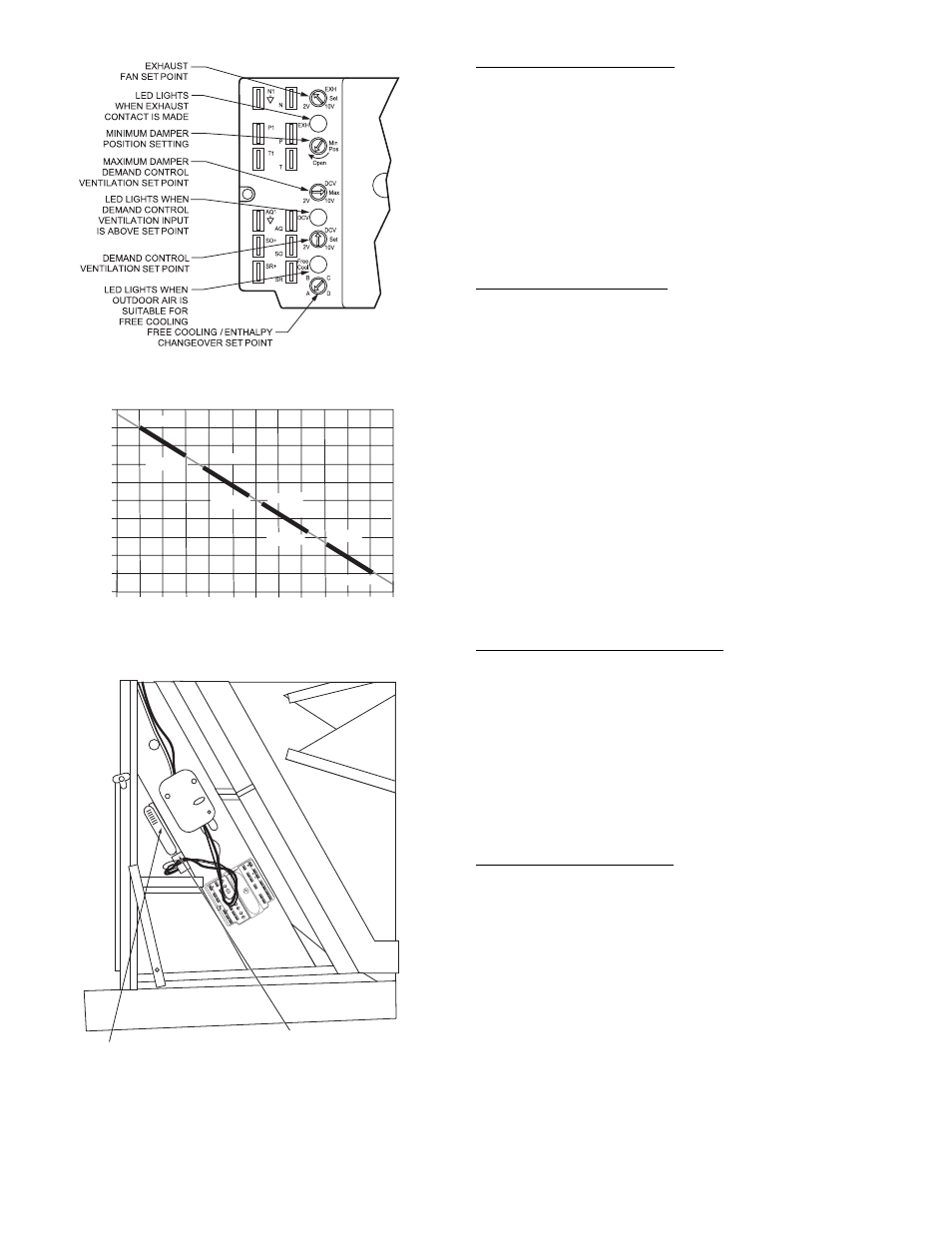
Exhaust Set Point Adjustment
The exhaust set point will determine when the exhaust fan
runs based on damper position (if accessory power exhaust is
installed). The set point is modified with the Exhaust Fan
Set Point (EXH SET) potentiometer. See Fig. 23. The set
point represents the damper position above which the
exhaust fan will be turned on. When there is a call for
exhaust, the EconoMi$erIV controller provides a 45 ± 15 sec-
ond delay before exhaust fan activation to allow the dampers
to open. This delay allows the damper to reach the appropri-
ate position to avoid unnecessary fan overload.
Fig. 23 — EconoMi$erIV Controller Potentiometer
and LED Locations
LED ON
LED ON
LED ON
LED ON
LED OFF
19
18
LED OFF
LED OFF
LED OFF
17
16
15
14
13
12
11
10
9
40
45
50
55
60
65
70
75
80
85
90
95
100
DEGREES FAHRENHEIT
mA
D
C
B
A
Fig. 24 — Outside Air Temperature
Changeover Set Points
IAQ
SENSOR
RETURN AIR
TEMPERATURE
OR ENTHALPY
SENSOR
TR
1
24
Va
c
COM
TR
24
Va
c
HO
T
1
2
3
4
5
EF
EF
1
+
_
P1
T1
P
T
N
EXH
2V
10
V
EX
H
Se
t
Set
2V
10
V
2V
10
V
DC
V
DC
V
Fr
ee
Co
ol
B
C
A
D
SO
+
SR
+
SR
SO
AQ1
AQ
DC
V
Mi
n
Po
s
Op
en
Ma
x
N1
Fig. 25 — Return Air Temperature or Enthalpy
Sensor Mounting Location