Bryant DURAPAC PLUS SERIES 542J User Manual
Page 26
—
26
—
D. High and Low-Pressure Switches
If either switch trips, or if the compressor overtemperature
switch activates, that refrigerant circuit will be automati-
cally locked out by the CLO. To reset, manually move the
thermostat setting.
E. Freeze Protection Thermostat (FPT)
An FPT is located on the indoor coil. It detects frost build-up
and turns off the compressor, allowing the coil to clear. Once
the frost has melted, the compressor can be reenergized by
resetting the CLO from the thermostat.
XI. RELIEF DEVICES
All units have relief devices to protect against damage from
excessive pressures (i.e., fire). These devices protect the high
and low side.
XII. CONTROL CIRCUIT, 24-V
This control circuit is protected against overcurrent by a
3.2-amp circuit breaker. Breaker can be reset. If it trips,
determine cause of trouble before resetting. Typical wiring is
shown in Fig. 40 and 41.
XIII. OPTIONAL HINGED ACCESS DOORS
When the optional service package is ordered or if the hinged
access doors option is ordered, the unit will be provided
with external and internal hinged access doors to facilitate
service.
Four external hinged access doors are provided. All external
doors are provided with 2 large
1
/
4
turn latches with folding
bail-type handles. (Compressor access doors have one latch.)
A single door is provided for filter and drive access. One door
is provided for control box access. The control box access door
is interlocked with the non-fused disconnect which must be
in the OFF position to open the door. Two doors are provided
for access to the compressor compartment.
Two internal access doors are provided inside the filter/drive
access door. The filter access door (on the left) is secured by 2
small
1
/
4
turn latches with folding bail-type handles. This
door must be opened prior to opening the drive access door.
The drive access door is shipped with 2 sheet metal screws
holding the door closed. Upon initial opening of the door,
these screws may be removed and discarded. The door is
then held shut by the filter access door, which closes over it.
XIV. REPLACEMENT PARTS
A complete list of replacement parts may be obtained from
any Bryant distributor upon request.
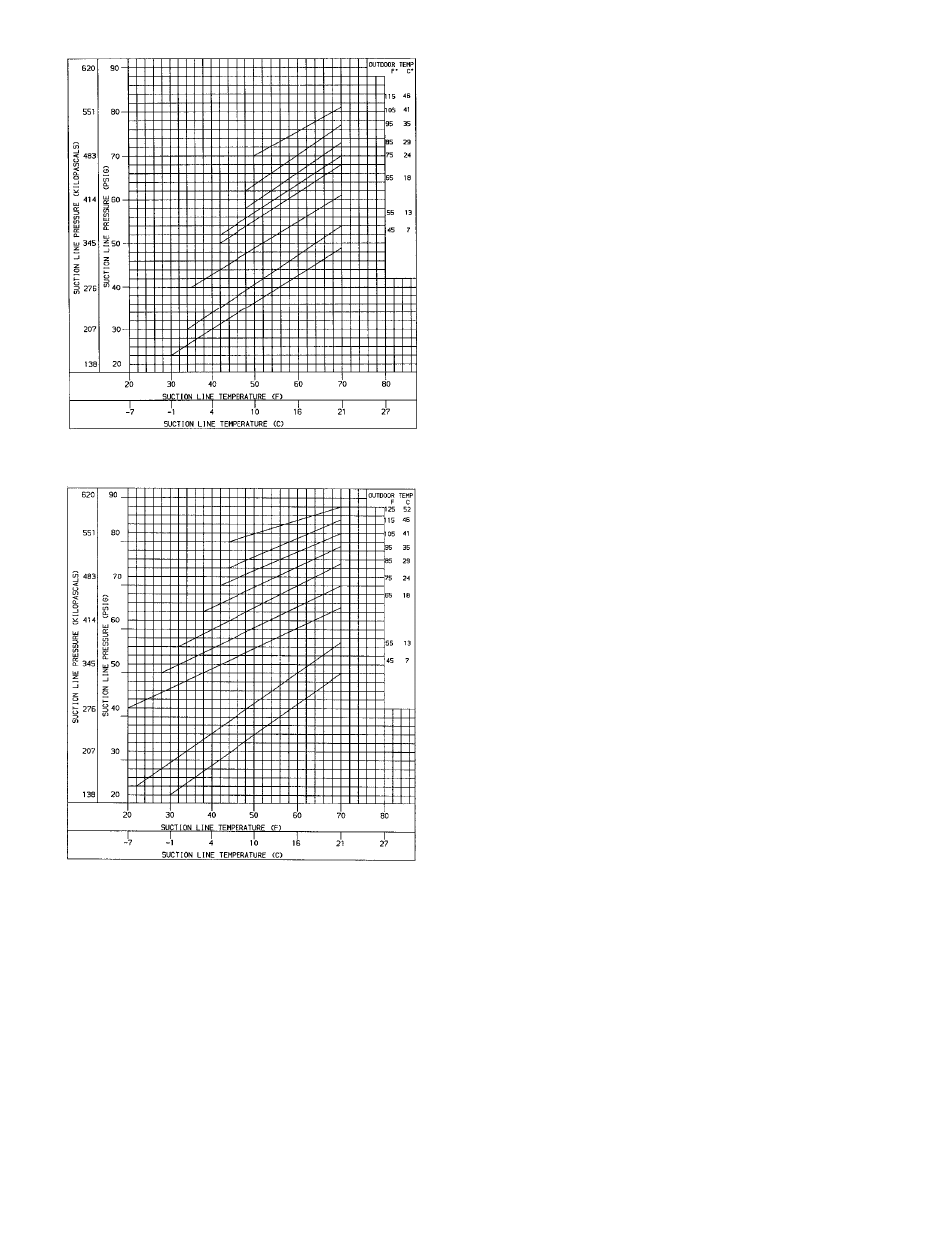
Fig. 38 — Cooling Charging Chart, 542J150 Units
Fig. 39 — Cooling Charging Chart, 542J180 Units