Bryant DURAPAC PLUS SERIES 542J User Manual
Page 11
—
11
—
A. Motormaster® I Control Installation
Install Field-Fabricated Wind Baffles
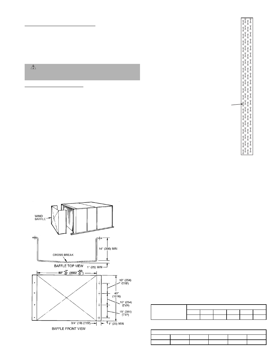
Wind baffles must be field-fabricated for all units to ensure
proper cooling cycle operation at low ambient temperatures.
See Fig. 18 for baffle details. Use 20-gage, galvanized sheet
metal, or similar corrosion-resistant metal for baffles. Use
field-supplied screws to attach baffles to unit. Screws should
be
1
/
4
-in. diameter and
5
/
8
-in. long. Drill required screw holes
for mounting baffles.
Install Motormaster I Controls
Only one Motormaster I control is required per unit. The
Motormaster I control must be used in conjunction with the
accessory 0° F low ambient kit (purchased separately). The
Motormaster I device controls outdoor fan no. 1 while out-
door fans no. 2 and 3 are sequenced off by the accessory 0° F
low ambient kit.
Accessory 0° F Low Ambient Kit — Install the accessory 0° F
low ambient kit per instruction supplied with accessory.
Sensor Assembly — Install the sensor assembly in the loca-
tion shown in Fig. 19.
Motor Mount — To ensure proper fan height, replace the
existing motor mount with the new motor mount provided
with accessory.
Transformer (460-V Units Only) — On 460-volt units a trans-
former is required. The transformer is provided with the
accessory and must be field-installed.
Motormaster I Control — Recommended mounting location
is on the inside of the panel to the left of the control box. The
control should be mounted on the inside of the panel, verti-
cally, with leads protruding from bottom of extrusion.
X. STEP 10 — ADJUST FACTORY-INSTALLED OPTIONS
A. Optional EconoMi$erIV
See Fig. 20 and 21 for EconoMi$erIV component locations.
NOTE:
These instructions are for installing the optional
EconoMi$erIV only. Refer to the accessory EconoMi$erIV or
EconoMi$er2 installation instructions when field installing an
EconoMi$erIV or EconoMi$er2 accessory.
To complete installation of the optional EconoMi$erIV, per-
form the following procedure.
1. Remove the EconoMi$erIV hood. Refer to Step 8 —
Install Outdoor-Air Hood on page 10 for information
on removing and installing the outdoor-air hood.
2. Relocate outdoor air temperature sensor from ship-
ping position to operation position on EconoMi$erIV.
See Fig. 20.
IMPORTANT:
Failure to relocate the sensor will result in the
EconoMi$erIV not operating properly.
3. Re-install economizer hood.
4. Install all EconoMi$erIV accessories. EconoMi$erIV
wiring is shown in Fig. 22.
Outdoor air leakage is shown in Table 4. Return air pressure
drop is shown in Table 5.
Table 4 — Outdoor Air Damper Leakage
Table 5 — Return Air Pressure Drop (in. wg)
CAUTION:
To avoid damage to the refrigerant coils
and electrical components, use recommended screw sizes
only. Use care when drilling holes.
DAMPER STATIC PRESSURE (in. wg)
0.2
0.4
0.6
0.8
1.0
1.2
LEAKAGE (cfm)
35
53
65
75
90
102
CFM
4500
5000
5400
6000
7200
7500
0.040
0.050
0.060
0.070
0.090
0.100
MOTORMASTER
SENSOR
LOCATION
HAIRPIN END
Fig. 19 — Motormaster I Sensor Locations
NOTES:
1. All sensors are located on the eighth
hairpin up from the bottom.
2. Field-installed tubing insulation is
required to be installed over the TXV
bulb and capillary tube for proper
operation at low ambients. Tubing
insulation is only required on the por-
tion of suction line located between
indoor and outdoor section.
NOTE: Dimensions in ( ) are in mm.
Fig. 18 — Wind Baffle Details