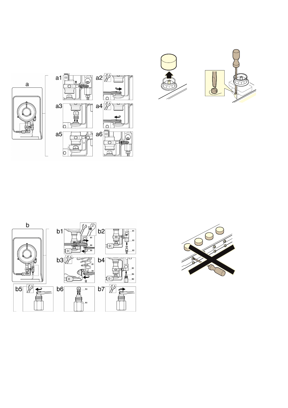
Changing the outer flame nozzle, Screw in the new outer flame nozzle. fig. a3-a4, Tighten the clamp screw. fig. a6 – Neff T69S86N0 User Manual
Page 7: Graphic, Changing the inner flame nozzle, Remove the pipe from the part m2. fig. b2, Screw in the new inner flame nozzle m4. fig. b6-b7, Adjustment of the taps, Set the control knobs to minimum, Never remove the valve reinforcing ring
7
Changing the outer flame nozzle
1.
Loosen the clamp screw to release the bushing by moving it
backwards to access the main nozzle easily. Fig. a1.
2.
Remove the outer flame nozzle by turning it towards the left.
Fig. a2-a3.
3.
Screw in the new outer flame nozzle. Fig. a3-a4.
4.
Adjust the distance of the airflow adjusting bushing L2
according to the value -Z-. Fig. a5.
5.
Tighten the clamp screw. Fig. a6.
Changing the inner flame nozzle
1.
Unscrew the part M3 from the threaded part M2; to do this,
hold the threaded part in the opposite direction.
2.
Remove the pipe from the part M2. Fig. b2.
3.
Disassemble the assembly of parts M2 and M4 from part M1.
Fig. b3-b4.
4.
Remove the inner flame nozzle M4 from part M2. Fig. b5-b6.
5.
Screw in the new inner flame nozzle M4. Fig. b6-b7.
Refit all the components, proceeding in the reverse order to
removal.
Adjustment of the taps
1.
Set the control knobs to minimum.
2.
Remove the control knobs from the taps. It has a flexible
rubber valve reinforcing ring. Press with the tip of the
screwdriver to access the tap's adjusting screw.
Never remove the valve reinforcing ring. The valve
reinforcing rings guarantee the watertightness of the
appliance's interior from liquids and dirt, which might
otherwise prevent its correct operation.
3.
Adjust the minimum ring setting by turning the by-pass screw
using a flat head screwdriver.
To adjust the minimum flame for N.G. replace the control
knob onto the spindle, light the gas and turn the control knob
to the small flame position. Screw the adjustment screw anti-
clockwise to estabilish a minimum stable flame position. The
flame should remain alight and not burn back to the injector
when the valve is turned quickly from ‘Full On’ to the
“Minimum flame” position and back a few times. To adjust
the minimum flame position for Propane Gas the screw must
be fully tightened down clockwise.
4.
Refit the control knobs.
If the by-pass screw cannot be accessed, disassemble the
glass panel and frame described in: Changing double flame
burner tips.
Never remove the tap spindle. In the event of a malfunction,
change the whole tap.
Important: After finishing, stick the sticker, indicating the new
gas type, close to the specifications plate.