3 precautions, 4 installation tips, 5 wiring 6 installation – BEA IS40P User Manual
Page 2: 1sensor tilt angle, Moun t, Cei li ng
1
Sensor Tilt Angle
LABEL
POWER (VAC / DC)
ACTIVATION RELAY
PRESENCE RELAY
12-24
12-24
COM
NO
NC
COM
NO
NC
COLOR
RED
BLACK
WHITE
GREEN
YELLOW
WHITE W/BLACK
STRIPE
GREEN W/BLACK
STRIPE
YELLOW W/BLACK
STRIPE
3 Precautions
This device IS NOT intended for use as a safety sensor.
Shut off all power before attempting any wiring procedures.
Maintain a clean & safe environment when working in public areas.
Constantly be aware of pedestrian/vehicle traffic around the area.
Always stop pedestrian/vehicle traffic through the doorway when performing tests that may result in unexpected reactions by the door.
ESD electrostatic discharge: Circuit boards are vulnerable to damage by electrostatic discharge. Before handling any board ensure
you dissipate your body’s charge.
Always check placement of all wiring before powering up to insure that moving parts will not catch any wires and cause damage to
equipment.
Ensure compliance with all applicable safety standards (i.e. ANSI A156.10 / 19) upon completion of installation.
DO NOT attempt any internal repair of the sensor. All repairs and/or component replacements must be performed by BEA Inc. Unau-
thorized disassembly or repair:
1. May jeopardize personal safety and may expose one to the risk of electrical shock.
2. May adversely affect the safe and reliable performance of the product will result in a voided product warranty.
4 Installation Tips
The sensor must be
firmly fastened to
prevent vibration.
The sensor must not have
any object likely to move or
vibrate in its sensing field.
DO NOT cover the sensor.
Page 2 of 6
75.5371.01 EN 20080505 (75.5370)
5 Wiring
6 Installation
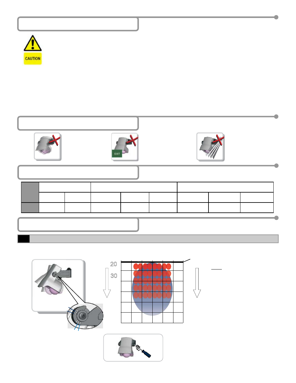
NOTE
: To obtain an IR pattern that’s
straight down (closest to the
door thershold); wall mounted
sensors need to be set at
20º, while sensors that are
extended out from the wall
should be set at around 15º.
It is important to adjust sensor angle first to position IR field correctly. Then adapt angle of radar field by using tilt angle adjustment screw.
15°
15°
30°
30°
C
EI
LI
NG
WALL MOUNT
When the angle of the sensor is
chosen, tighten the screws firmly.
Mounting height: 16 ft.
Sensitivity: 9
Microwave field angle: 30°
MOUN
T
3.25
6.50
9.75
13.00
19.70
16.30
3.25
0
3.25
6.50
6.50
ft.
ft.
20∞
45∞
30∞