BEA SBK-30R User Manual
Sbk-30, 3 installation, User’s guide 1 description
3 Installation
SBK-30
USER’S GUIDE
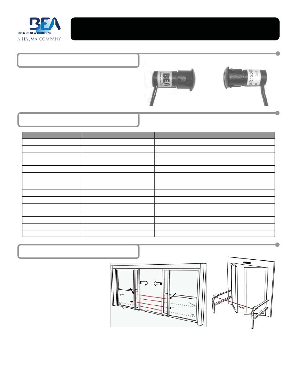
1 Description
75.5179.05 20080415
Page 1 of 2
The SBK-30 (10.1029) is a self-contained infrared beam set that
may be used for various applications, most commonly automatic
pedestrian doors. The beams fi t easily into a pre-drilled ½” hole
and are a snap fi t. Wiring is by a quick disconnect cable that can
be daisy-chained up to 30’ (in 15’ increments). The beams offer
an LED indication at their back side for ease of alignment and
troubleshooting.
1.
Pre-drill a ½” hole at the desired mounting
location.
2.
When using more than one set of beams,
alternate the beam orientation as shown
at right.
3.
Route the long cable from its termination
point to the beam mounting location.
4.
Plug the beam cable in via the snap
together connector.
5.
Install the beam into the ½” hole and press
the beam until it clicks into the opening.
Typically, the wall thickness of the drilled
material should not exceed 1/8”.
PHOTOELECTRIC BEAMS FOR GUIDE RAIL APPLICATIONS
Emitter A
Receiver B
Emitter C
Receiver
A
Emitter B
Receiver
D
Receiver C
Emitter D
Beam A: Between 45” and 55” from floor
Beam B, C: Between 6” and 12” from any other beam
Beam D: Between 6” and 28” from floor
For sliding doors, ANSI/BHMA A156.10-2005 states the lowest beam should be between 6” (152mm) and 28” (711mm) from the fl oor. The
distance between the highest beam and the fl oor should be between 45” (1143mm) and 55” (1397mm). Other beams between the lowest and
highest should not be greater than 6” (152mm) and 12” (305mm) apart from any other beam.
EMITTER
(SBK-30T)
RECEIVER
(SBK-30R)
2 Specifi cations
SBK30R / SBK30T BEAM
SBK30 INTERFACE MODULE
TECHNOLOGY
Active Infrared: 880nm
One SBK30 Beam Set
DETECTION MODE
Presence Detection
N/A
SUPPLY VOLTAGE
10 to 30 VDC
12 to 24 VAC/DC
CURRENT CONSUMPTION
Receiver: 15mA / Emitter: 9mA
53 mA MAX
OUTPUT CONSUMPTION
NPN Output, Light Operate
1 Relay, (NC/NO Contacts), 0-30 second adjustable hold time
OUTPUT RATING
100 mA max. Total Output Load
Rated Load:
0.3A@125VAC (NO Contacts) 0.3A@125VAC (NC Contacts)
1.0A@ 30VDC (NO Contacts) 1.0A@ 30VDC (NC Contacts)
RANGE (BEAM SEPARATION)
30 feet
N/A
OUTPUT RESPONSE TIME
1 mS
3 mS
MATERIAL
ABS Plastic & Acrylic Lense
PCB with shrink rube
CONNECTION
Molex 3-Conductor w/ 26 AWG Wire
One Beam Pair
INGRESS PROTECTION
IP65 (NEMA 4)
IP65 (NEMA 4 Enclosure)
OPERATING TEMPERATURE
-30F to +130F
-30F to +130F
WIRING
8” Wire on Beam / 15’ Extension Cable
None Included