Bryant 373LAV User Manual
Page 9
IX.
GAS PIPING
Gas piping must be installed in accordance with national and local
codes. Refer to the current edition of the NFGC.
Canadian installations must be installed in accordance with NSC-
NGPIC and all authorities having jurisdiction.
Refer to Table 5 for recommended gas pipe sizing. Risers should
be used to connect to the furnace and to the meter.
CAUTION:
If a flexible connector is required or al-
lowed by the authority having jurisdiction, black iron
pipe shall be installed at the gas valve and extend a
minimum of 2 in. outside the furnace casing.
WARNING:
Use the proper length of pipes to avoid
stress on the gas control manifold. Failure to follow this
warning could result in a gas leak, causing fire, explosion,
personal injury, or death.
CAUTION:
Connect the gas pipe to the furnace using a
backup wrench to avoid damaging gas controls.
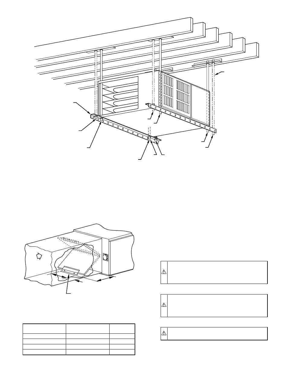
Fig. 10—Horizontal Crawlspace Installation on Hanger Rods
A96633
NOTES:
ANGLE
IRON OR
EQUIVALENT
ROD LOCATION
USING DIMPLE
LOCATORS
(SEE DIMENSIONAL
DWG FOR
LOCATIONS)
3
⁄
8
-IN. ROD
1. A 1 In. clearance minimum between top of
furnace and combustible material.
2. The entire length of furnace must be
supported when furnace is used in horizontal
position.
3
/
8
-IN. HEX NUT
& WASHER (4)
REQD PER ROD
(A) PREFERRED ROD LOCATION
(B) ALTERNATE ROD LOCATION
(A)
(B)
(A)
(B)
(B)
(A)
(A)
(B)
TABLE 4—FILTER RETAINER (IN.)
FURNACE
CASING WIDTH
FILTER SIZE
AND QUANTITY
D
14-3/16
(2) 14 X 20 X 1
14-3/8
17-1/2
(2) 14 X 20 X 1
13-3/8
21
(2) 16 X 20 X 1
11-5/8
24-1/2
(2) 16 X 20 X 1
10-1/4
Fig. 11—Horizontal Filter Arrangement
A82173
FIELD-SUPPLIED
FILTER RETAINERS
AIRFLOW
D
12
″
4
″
—9—