Bryant 373LAV User Manual
Page 10
WARNING:
Never purge a gas line into a combustion
chamber. Never use matches, candles, flame, or other
sources of ignition to check for gas leakage. Use a
soap-and-water solution to check for gas leaks. Failure to
follow this warning could result in fire, explosion, per-
sonal injury, or death.
Joint compounds (pipe dope) should be applied sparingly and only
to the male threads of the joints. This pipe dope must be resistant
to the action of propane gas.
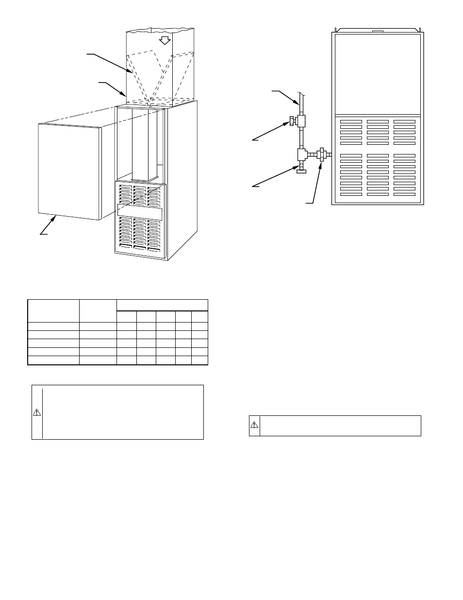
An accessible manual shutoff valve MUST be installed upstream
of the furnace gas controls and within 72 in. of the furnace. A
1/8-in. NPT plugged tapping, accessible for test gage connection,
MUST be installed immediately upstream of the gas supply
connection to the furnace and downstream of the manual shutoff
valve. Place a ground joint union between the gas control manifold
and the manual shutoff.
Install a sediment trap in the riser leading to the furnace. The trap
can be installed by connecting a tee to the riser leading from the
furnace. Connect a capped nipple into the lower end of the tee. The
capped nipple should extend below the level of the gas controls.
(See Fig. 13.)
Piping should be pressure tested in accordance with local and
national plumbing and gas codes before the furnace has been
attached. If the pressure exceeds 0.5 psig (14-in. wc), the gas
supply pipe must be disconnected from the furnace and capped
before the pressure test. If the test pressure is equal to or less than
0.5 psig (14-in. wc), turn off electric shutoff switch located on the
gas valve before the test. It is recommended that the ground joint
union be loosened before pressure testing.
After all connections have been made, purge the lines and check
for gas leakage with regulated gas supply pressure.
X.
ELECTRICAL CONNECTIONS
A.
115-v Wiring
Refer to the unit rating plate or Table 6 for equipment electrical
requirements. The control system requires an earth ground for
proper operation.
CAUTION:
Do not connect aluminum wire between
disconnect switch and furnace. Use only copper wire.
Make all electrical connections in accordance with the current
edition of the National Electrical Code (NEC) ANSI/NFPA
70-1999, and any local codes or ordinances that might apply. For
Canadian installations, all electrical connections must be made in
accordance with Canadian Electrical Code CSA C22.1, or authori-
ties having jurisdiction.
NOTE:
Proper polarity must be maintained for 115-v wiring. If
polarity is incorrect, control center fault code indicator light will
flash rapidly and furnace will not operate.
Fig. 12—Downflow Filter Arrangement
A88486
RETURN-AIR
PLENUM
AIRFLOW
ACCESS DOOR
INSTALLATION
POSITION
OF FILTERS
TABLE 5—MAXIMUM CAPACITY OF PIPE *
NOMINAL IRON
PIPE SIZE
(IN.)
INTERNAL
DIAMETER
(IN.)
LENGTH OF PIPE (FT)
10
20
30
40
50
1/2
0.622
175
120
97
82
73
3/4
0.824
360
250
200
170
151
1
1.049
680
465
375
320
285
1-1/4
1.380
1400
950
770
660
580
1-1/2
1.610
2100
1460
1180
990
900
* Cubic ft of gas per hr for gas pressures of 0.5 psig (14-in. wc) or less, and a
pressure drop of 0.5-in. wc (based on a 0.60 specific gravity gas). Ref: Table
10-2 NFPA 54/ANSI Z223.1-1996.
Fig. 13—Typical Gas Pipe Arrangement
A89414
GAS
SUPPLY
MANUAL
SHUTOFF
VALVE
(REQUIRED)
SEDIMENT
TRAP
UNION
—10—
→
→