Bryant 373LAV User Manual
Page 7
A.
Construct a Working Platform
Construct working platform on location where all required
furnace clearances are met. (See Fig. 2 and 8.)
B.
Install Furnace
1. Position furnace in desired location.
2. Connect gas supply pipe. See Fig. 8 for typical piping entry.
3. Install field-supplied filter retainers as indicated in Fig. 11
and Table 4 before connecting return-air duct to furnace.
4. Connect supply- and return-air ducts.
5. Install 24- X 24-in. sheet metal shield on platform in front
of louvered control panel as shown in Fig. 8.
VII.
HORIZONTAL CRAWLSPACE INSTALLATION
The furnace can be installed horizontally with either the LH or RH
side up. In a crawlspace, the furnace can either be installed on
suitable blocks or pad (See Fig. 9.) or hung from the floor joist.
(See Fig. 10). The furnace can be suspended from each corner by
hanger bolts (4 each 3/8-in. all-thread rod) cut to desired length,
1 X 3/8-in. flat washer, 3/8-in. lockwasher, and 3/8-in. nut.
Dimples are provided for hole locations. (See Fig. 1.)
Since horizontal crawlspace installation is very similar to the attic
installation, refer to Section VI. The installation of a sheet metal
shield in front of the louvered control panel is covered in Section
VI. For a crawlspace installation, this same sheet metal shield must
be installed above the louvered control panel. Extend the sheet
metal shield over the furnace top far enough to cover the gas pipe
entry hole.
VIII.
FILTER ARRANGEMENT
WARNING:
Never operate unit without a filter or with
filter access door removed. Failure to follow this warning
could result in fire, personal injury, or death.
The 2 factory-supplied filters are shipped in the blower compart-
ment. After the return-air duct has been connected to the furnace,
install the filters in a V-formation inside the return-air plenum. See
Fig. 11 and Table 4 for horizontal applications. Horizontal filter
retainers must be field supplied. See Fig. 12 for downflow
applications.
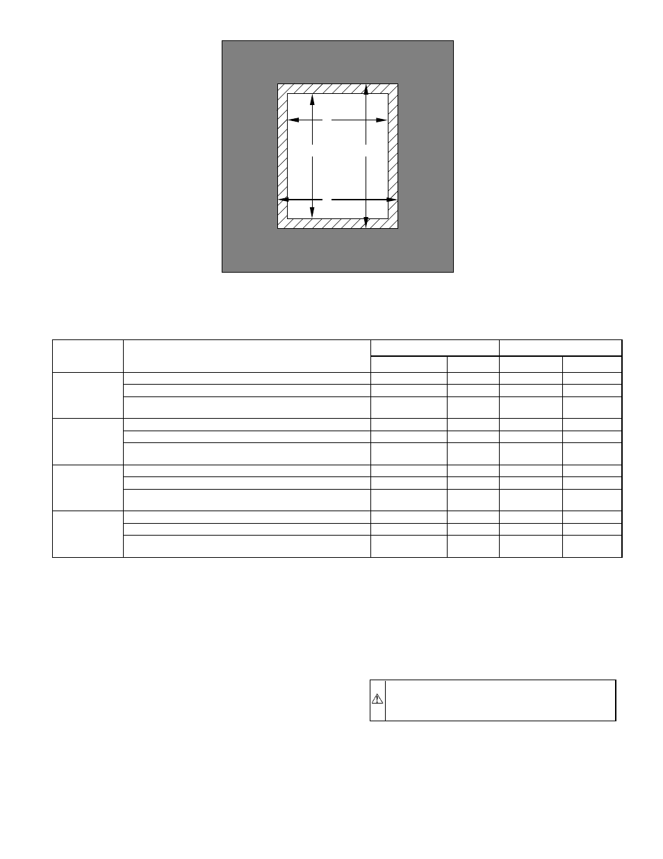
TABLE 3—OPENING DIMENSIONS (IN.)
FURNACE
CASING
WIDTH
APPLICATION
PLENUM OPENING
FLOOR OPENING
A
B
C
D
14-3/16
Non-Combustible Flooring
12-11/16
19
13-3/8
19-5/8
Combustible Flooring Using KGASB Subbase
11-13/16
19
13-7/16
20-3/8
Combustible Flooring with CD5 or CK5 Coil Assembly or
KCAKC Coil Box
12-5/16
19
13-5/16
20
17-1/2
Non-Combustible Flooring
16
19
16-5/8
19-5/8
Combustible Flooring Using KGASB Subbase
15-1/8
19
16-3/4
20-3/8
Combustible Flooring with CD5 or CK5 Coil Assembly or
KCAKC Coil Box
15-1/2
19
16-1/2
20
21
Non-Combustible Flooring
19-1/2
19
20-1/8
19-5/8
Combustible Flooring Using KGASB Subbase
18-5/8
19
20-1/4
20-3/8
Combustible Flooring with CD5 or CK5 Coil Assembly or
KCAKC Coil Box
19
19
20
20
24-1/2
Non-Combustible Flooring
23
19
23-5/8
19-5/8
Combustible Flooring Using KGASB Subbase
22-1/8
19
23-3/4
20-3/8
Combustible Flooring with CD5 or CK5 Coil Assembly or
KCAKC Coil Box
22-1/2
19
23-1/2
20
Fig. 5—Floor and Plenum Opening Dimensions
A96283
PLENUM
OPENING
C
A
B
D
FLOOR
OPENING
—7—
→