Bryant 373LAV User Manual
Page 18
EXAMPLE:
92,000 Btuh input furnace installed at 4300 ft.
Furnace Input
Rate at
Sea Level
X
Derate
Multiplier
Factor
=
Furnace Input Rate
at Installation
Altitude
92,000
0.82
75,440
CANADA
At installation altitudes from 2000 to 4500 ft, this furnace must be
derated 10 percent by an authorized Gas Conversion Station. To
determine correct input rate for altitude, see example above and
use 0.90 as derate multiplier factor.
a. Turn off all other gas appliances and pilots.
b. Start furnace and let operate for 3 minutes.
c. Measure time (in sec) for gas meter test dial to complete
1 revolution.
d. Refer to Table 9 for cu ft of gas per hr.
e. Multiply gas rate (cu ft/hr) X heating value (Btu/cu ft)
using natural gas heating value from local gas
utility/supplier.
EXAMPLE: (0—2000 ft altitude)
Btu heating input = Btu/cu ft X cu ft/hr
Heating value of gas = 1050 Btu/cu ft
Time for 1 revolution of 2-cu ft dial = 82 sec
Gas rate = 88 cu ft/hr (from Table 9)
Btu heating input = 88 X 1050 = 92,400 Btuh
In this example, the orifice size and manifold pressure
adjustment is within
±
2 percent of the furnace input rate.
2. Set temperature rise.
Furnace must operate within range of temperature rise
specified on the unit rating plate. Determine the air tem-
perature rise as follows.
a. Place duct thermometers in return and supply ducts as
near furnace as possible. Be sure thermometers do not
"see" heat exchangers so that radiant heat does not affect
thermometer readings. This is particularly important
with straight-run ducts.
b. When thermometer readings stabilize, subtract return-air
temperature from supply-air temperature to determine
temperature rise.
c. Adjust air temperature rise by adjusting blower speed.
Increase blower speed to reduce temperature rise. De-
crease blower speed to increase temperature rise.
WARNING:
Disconnect the electrical power before
changing the speed tap. Failure to follow this warning
could result in personal injury.
d. To change blower motor speed selections for heating
mode, remove blower motor lead from control HEAT
terminal. (See Fig. 14.) Select desired blower motor
speed lead from 1 of the other terminals and relocate it
to HEAT terminal. See Table 10 for lead color identifi-
cation. Reconnect original lead on SPARE terminal.
Follow this same procedure for proper selection of COOL
speed selection.
CAUTION:
Recheck temperature rise. It must be within
limits specified on unit rating plate. Recommended op-
eration is at midpoint of rise or above.
TABLE 8—MODEL 373LAV ORIFICE SIZE† AND MANIFOLD PRESSURE FOR CORRECT INPUT
(Continued)
(Tabulated Data Based on 23,000 BTUH Per Burner, Derated 4 Percent per 1000 Ft Above Sea Level)*
ALTITUDE
RANGE
(FT)
AVG GAS
HEAT VALUE
AT ALTITUDE
(BTU/CU FT)
SPECIFIC GRAVITY OF NATURAL GAS
0.58
0.60
0.62
0.64
0.66
Orifice
No.
Manifold
Pressure
Orifice
No.
Manifold
Pressure
Orifice
No.
Manifold
Pressure
Orifice
No.
Manifold
Pressure
Orifice
No.
Manifold
Pressure
U.S.A.
Only
575
43
3.0
43
3.1
43
3.2
43
3.3
43
3.4
600
43
2.7
43
2.8
43
2.9
43
3.0
43
3.1
9001
625
43
2.5
43
2.6
43
2.7
43
2.8
43
2.8
650
43
2.3
43
2.4
43
2.5
43
2.6
43
2.6
to
675
43
2.1
43
2.2
43
2.3
43
2.4
43
2.4
700
48
3.8
43
2.1
43
2.1
43
2.2
43
2.3
10,000
725
48
3.5
48
3.6
48
3.7
43
2.1
43
2.1
750
49
3.8
48
3.4
48
3.5
48
3.6
48
3.7
775
49
3.6
49
3.7
49
3.8
48
3.4
48
3.5
* For size 060135 only, input is 22,500 Btuh per burner. Deduct 0.1-in. wc from manifold pressure shown in table. Change orifice size if manifold pressure falls below 3.2-in.
wc on altitudes up to 2000 ft, otherwise change orifice size if manifold pressure falls below 2.0-in. wc.
† Orifice sizes shown in BOLD are factory installed.
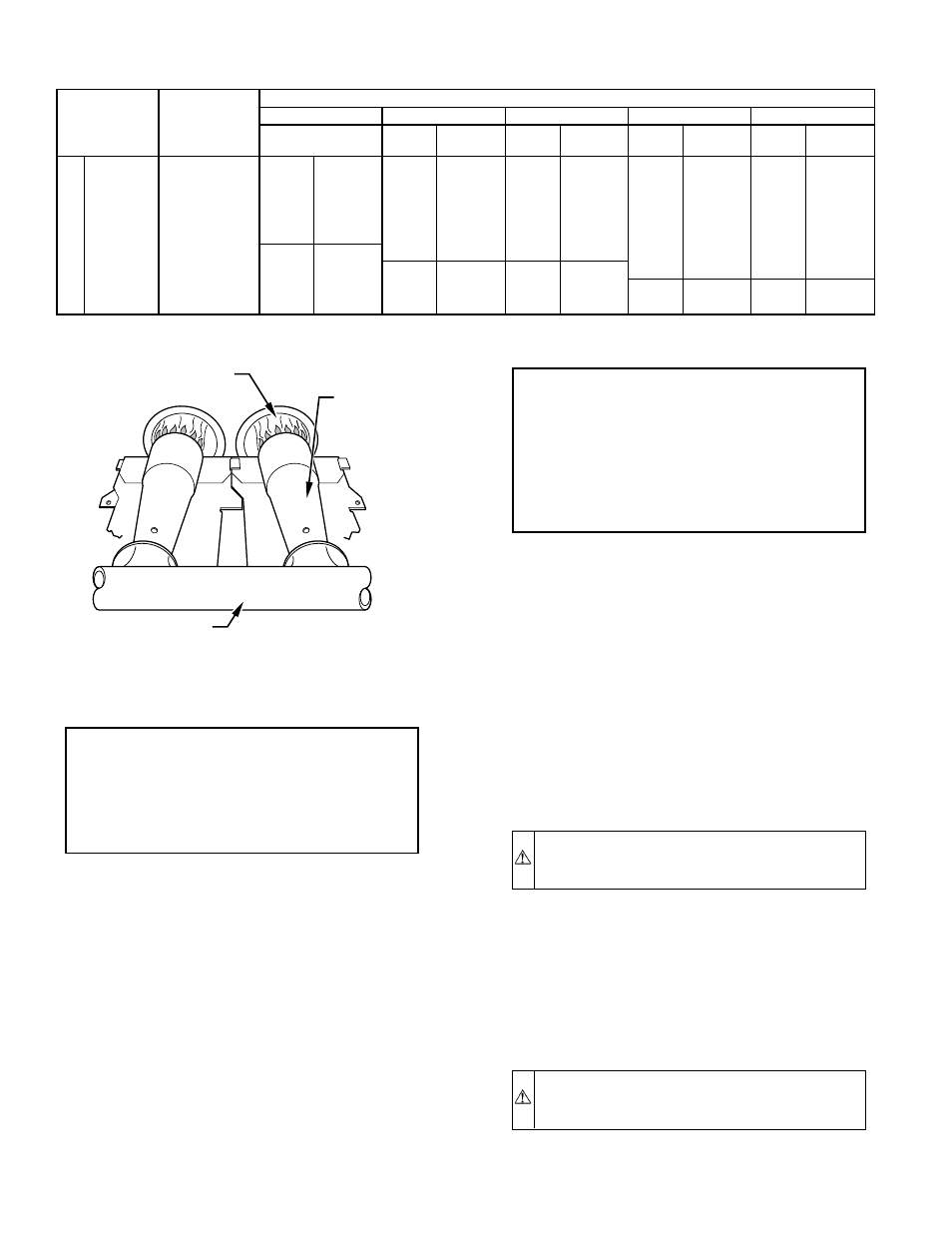
Fig. 18—Burner Flame
A89020
BURNER FLAME
BURNER
MANIFOLD
—18—