AEG Rear Camera System RV 3.5 User Manual
Page 23
Caution! The location of the monitor
may not impair the visibility of the
driver! Further, do not impair the func-
tionality and operation of equipment, control units
and systems inside the vehicle. Follow applicable
laws and safety regulations for vehicles!
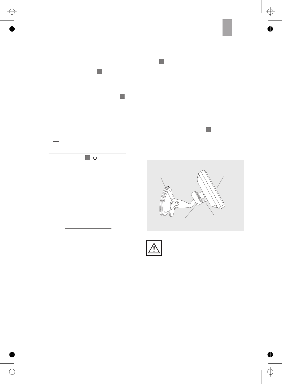
Image 12
Monitor locking
lever
Monitor
swivels
Locking screw
Locking
lever
▪
Insert the square monitor socket on the monitor
arm into the designated notch at the back
of the monitor. Now slide the monitor bracket
upward until it catches (see image 12).
▪
Open the locknut and adjust the monitor to the
desired viewing angle. Now tighten the locknut
to secure the monitor.
▪
Clean the area of the windshield where you
would like to attach the suction cup base. Now
press the suction cup base onto the windshield
and move the locking lever toward the suction
cup base.
▪
Now plug the monitor cable into the vehi-
cle's outlet (12 V). Place the monitor cable so
as not to impact or jeopardize the safety of the
vehicle and its passengers.
4.2 Installing the monitor
Step 8: Installing the transmitter
Remove the protective film from the adhesive strip
at the top of the transmitter and affix in a protec-
ted location behind the trunk trim. Also secure the
transmitter with two cable ties . Be sure there
are no electrical loads in the direct vicinity of the
transmitter to avoid impairing the transmission.
Now secure the camera and transmitter cables
run in the void of the trunk with cable ties . The
cables run may not interfere with the vehicle‘s
functionality!
Step 9:Check the transmitter power
supply cable
First engage the hand brake and be sure the ve-
hicle is not shifted into gear. Vehicles with auto-
matic transmission must be in ”P“ for parking
lock. Turn the ignition to II but do not start the
engine! Push the button ( ) to power on the
monitor. If the transmitter correctly connected, a
signal will now be transmitted to the monitor
when putting the car into reverse and the monitor
displays the camera‘s viewing range.
If no image is displayed on the monitor you may
further check the camera power supply with the
hand brake engaged (or vehicle in ”P“ for park-
ing lock on vehicles with automatic trans-mission),
ignition turned (II) and the vehicle in reverse with
a simple test. Do not start the engine! Completely
cover the camera with both palms cupped to
darken the camera surroundings and activate the
night vision sensor. Leave a slight opening be-
tween your thumbs and look into your palms. If
the camera is active, all 7 LEDs around the
camera will light up red. If the LEDs do not light
up check the camera‘s cable and terminal
connections. Also see item 4.7 on page 26.
4
4
12
10
2
GB
23
97152_R
ckfahrkamera_RV3.5_ Manual _07_03_12_Print
Mittwoch, 7. M
rz 2012 11:42:17