Vollrath SU444 Water Cooled User Manual
Page 16
Owner’s Manual #513684
10
SU444I2 Model Machines
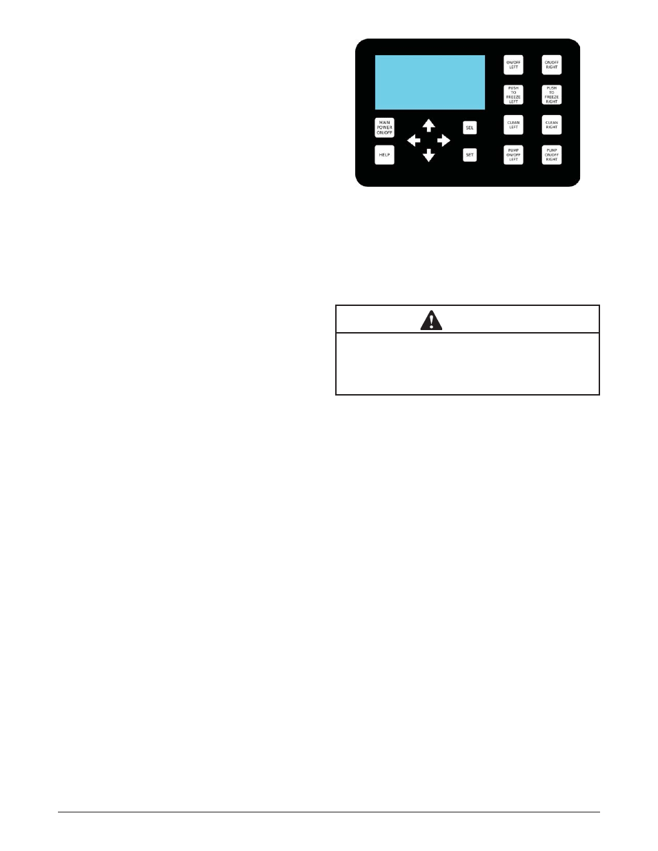
A. INTELLITEC2™ TOUCHPAD
Main Power On/Off
The Main Power button is used to supply power to the
IntelliTec2™ control, the freezing cylinder circuits and
the storage refrigeration system. When the machine is
fi rst plugged in, the control defaults to the On status with
power to the hopper only. If the Main Power On/Off button
is pressed when the machine is on, the machine will turn
off and a status message will be displayed on the screen.
Help
Pressing the Help button will display help information
dependant on the cursor’s location. Pressing the Help
button again will exit the help screen.
Selection Button (SEL)
The SEL button is used by technicians to select menu
options.
Set Button (SET)
The SET button is used by technicians to save changes
when modifying control settings.
On/Off Button
Power to the freezing cylinders can then be controlled
with the On/Off Left and On/Off Right switches.
Push to Freeze Button
Pressing the PUSH TO FREEZE button initiates “Serve
Mode”.
Clean Button
The CLEAN button initiates “Clean Mode”.
Arrow Buttons (
)
The arrow buttons are used by technicians to navigate
through the control readings and settings.
B. SPIGOT SWITCH
The spigot switch is mounted to the spigot cam assembly
behind the header panel. When the spigot is opened to
dispense product, the spigot switch opens and the “Serve
Mode” begins.
C. DISPENSE RATE ADJUSTOR (LEFT SIDE)
The dispense rate adjustor is located under the header
panel, to the immediate right of the spigot handles. Turning
the knob counterclockwise will decrease the dispense rate.
D. BLENDER POWER ON/OFF CIRCUIT BREAKER
(RIGHT SIDE)
The Blender Power Off/On and Circuit Breaker switch is
a two position toggle switch used to supply power to the
blender. When the switch is in the OFF position, there is
no power to the blender. When the switch is in the ON
position, the blender will operate any time the spigot
handle is pushed to the right. This switch also serves as
a circuit breaker to interrupt power if the rotation of the
blender agitator becomes hindered..
E. USB ACCESS PORT
The USB access port is located on the right side panel
of the machine. The port is used by technicians to import
fi rmware and export machine statistics.
3.3 DISASSEMBLY OF LEFT SIDE
WARNING
Moving machinery can grab, mangle and dismem-
ber. Make sure the display shows that the machine
is off. If it is not, press and hold the Main Power
button until the display shows that it is off.
Before using the machine for the fi rst time, complete
machine disassembly, cleaning and sanitizing proce-
dures need to be followed. Routine cleaning intervals
and procedures must comply with the local and state
health codes. Inspection for worn or broken parts should
be made at every disassembly of the machine. All worn
or broken parts should be replaced to ensure safety to
both the operator and the customer and to maintain good
machine performance and a quality product.
To disassemble the left side, refer to the following steps:
A. REMOVE FRONT DOOR AND AUGER
1.
Remove the knobs on the front door and remove
the door by pulling it off the studs.
2.
Remove the air bleed valve by unscrewing the
knob while holding the valve stem from behind.
Remove the compression spring and push the
air bleed valve through the rear of the front door.
3.
Remove the spigot through the bottom of the front
door. Remove all o-rings from the spigot and the
air bleed valve.
4.
Remove the front auger support and plastic
bearing.
5.
Remove the auger by pulling slowly and rotating
out of the machine barrel. As the auger is
withdrawn, remove each plastic fl ight and spring
from the auger. Be careful not to scratch inside of
machine barrel when removing fl ights or auger.
Remove the spring from each auger fl ight.
Figure 3-2 IntelliTec2™ Control