Vollrath SU412 User Manual
Page 21
15
A.
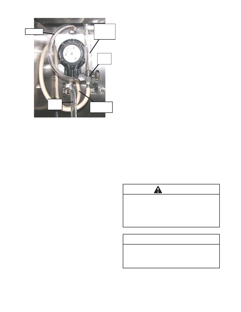
Mix Operation: The peristaltic mix pump contains
one continuous mix pump hose. When looking at
the face of the peristaltic mix pump, the left side
of the hose is the mix intake or pickup. The right
side of the hose is the mix discharge. Mix is drawn
up the pickup side of the hose and transferred
through the discharge side to the machine (Fig.
3-10).
B.
Air Operation: The air compressor operates
whenever the peristaltic mix pump is running.
Air enters through a check valve on the piston
downstroke. The air is discharged through a
second check valve, on the piston upstroke. The
air and mix join at the tee and then travel to the
machine.
C.
The overrun adjustment is preset at the factory.
If an adjustment becomes necessary, refer to
Section 4.
3.14 MIX PUMP CLEANING
NOTICE
Any cleaning procedure must always be followed
by sanitizing before fi lling machine with mix. (Refer
to section 3.3)
The mix pump is approved for CIP (clean in place). It is
thoroughly cleaned when the detergent solution is pumped
through the machine. We recommend completely disas-
sembling the pump and disconnecting tubing every 14
days for inspection of parts to confi rm the CIP has been
properly performed. If any residue is detected, clean or
replace those parts as outlined below.
A.
Place the Main Power OFF/ON and Freezing
Cylinder OFF/ON switches in the ON position
and press the CLEAN button. Allow the auger to
agitate for 5 to 10 minutes.
B.
Remove the suction tube from the mix container.
Open the spigot to remove the mix remaining in
the freezing cylinder.
C.
Pump 2 gallons (7.5 liters) of potable water through
machine until the water comming out of the spigot
is clear.
D.
Pump 2 gallons (7.5 liters) of 90° to 110°F (32°C
to 43°C) detergent solution through the machine.
The use of soft water is recommended, along with
dishwashing detergents such as “Joy,” “Dawn,”
or equivalent.
E.
Place the mix pump switch in the OFF position.
Open the spigot to relieve the remaining pressure.
F.
Press the CLEAN button to stop the auger and
place the Main Power OFF/ON and Freezing
Cylinder OFF/ON switches in the OFF position.
3.15 DISASSEMBLY AND INSPECTION OF
REMOVABLE PARTS
Inspection of removable parts should be made whenever
maintenance is performed or when the pump requires
disassembly.
NOTE
If the mix line or air line is diffi cult to remove, soften
the tubing with a rag soaked in hot water. Hose
connections may be sprayed with Haynes Sanitary
Lubricant for ease of removal.
WARNING
Hazardous Moving Parts
Revolving pump head can grab, mangle, and
cause serious crushing injury. The Main Power Off/
On switch must be placed in the OFF position for
cleaning and power must be disconnected when
disassembling or servicing.
CAUTION
System Under Pressure
Never disconnect hoses from the machine or the
pump without fi rst opening the spigot to relieve
pressure.
Figure 3-10 Mix Pump Hose Routing
Air Line
Mix
Intake
Mix
Discharge
3-way
Tee
Air/Mix to
Freezing
Cylinder