Vollrath SU412 User Manual
Page 14
8
C. SPIGOT SWITCH
The spigot switch is mounted to the spigot cam assembly
behind the header panel. When the spigot is opened to
dispense product, the spigot switch opens and the “Serve
Mode” begins.
D. BLENDER POWER OFF/ON AND CIRCUIT BREAKER
SWITCH
The Blender Power Off/On and Circuit Breaker switch
is a two position toggle switch used to supply power to
the blender (SU412 models). When the switch is in the
OFF position, there is no power to the blender. When the
switch is in the ON position, the blender will operate any
time the spigot handle is pushed to the right. This switch
also serves as a circuit breaker to interrupt power if the
rotation of the blender agitator becomes hindered.
E. CAB OFF INDICATOR LIGHT
A fl ashing light indicates the Main Freezer Power Switch
is in the OFF position; no refrigeration is being supplied
to the cab. Place the Main Freezer Power switch in the
ON position for cab refrigeration.
F. PUMP SWITCH
The pump motor switch is the toggle switch located on
the front of the machine. When the switch is placed in
the OFF position, the pump will not run. When the switch
is placed in the ON position, the pump will run until the
preset pressure is reached. It then cycles on and off as
product is drawn to maintain that pressure.
G. PUSH TO FREEZE BUTTON
The PUSH TO FREEZE button is a membrane or snap
switch used to initiate “Serve Mode”.
NOTE
After the PUSH TO FREEZE button is pressed,
the drive motor starts. After a 3-second delay, the
compressor will start.
H. LEDS
The membrane switch (touchpad) features two lights: a
green LED and an amber LED. The green LED is lit dur-
ing “Serve Mode”. During freeze down, it is not lit. When
product consistency approaches 90% in the freezing
cylinder, the green LED fl ashes. The amber LED is on
during all other modes. Both LEDs alternatively fl ash if
an error occurs or if the freezing cylinder is off.
I. CLEAN BUTTON
The CLEAN button is a membrane, or snap switch. When
the button is pressed, the freezing cycle stops and the
drive motor will start. A CLEAN message will display on
the LCD screen along with a 5-minute countdown timer.
If the button is pressed again, the timer will reset. To
exit the CLEAN mode, turn the Freezing Cylinder OFF/
ON switch to the OFF position. If the machine is left in
CLEAN for more than 20 minutes, an error code (E4) will
be displayed on the display panel. Place the Freezing
Cylinder OFF/ON switch in the OFF position and back in
the ON position to clear this error.
J. DRIVE MOTOR OVERLOAD
The internal drive motor overload will trip if the drive
motor is overloaded. It will reset after approximately 10-
12 minutes. If the drive motor continues to trip, refer to
Troubleshooting in Section 5.
K. MIX LOW LIGHT INDICATOR
A MIX LOW message will appear on the LCD display to
alert the operator of a low mix condition. The message
will display when there is approximately one gallon of
mix left in the mix container or when one bag of the Bag
Connection System (BCS) is empty. When the MIX LOW
message is displayed, refi ll the container or replace a
bag immediately.
L. MENU NAVIGATION BUTTONS
The Menu Navigation Buttons allow the user to display
information regarding the machine’s status of operation
as well as adjust product consistency (Fig. 3-2).
Selection Button (SEL) The SEL button is used in
combination with the left arrow button to enter into
the settings of the IntelliTec control. This button is
also used to navigate through the control settings
menu.
Set Button (SET) The SET button is used to save
a change made to the product consistency setting.
It is also used to save changes when modifying
control settings.
Left Arrow Button (
) If the left arrow button is
pressed for 5 seconds, the display will remain lit.
To turn the light off, press the left arrow button for
5 seconds. The left arrow button is used primarily
to navigate through the control settings.
Up Arrow Button (
) After pressing the SET
button, the up arrow button will change the value
of the product consistency setting. This button
is used primarily to navigate through the control
settings.
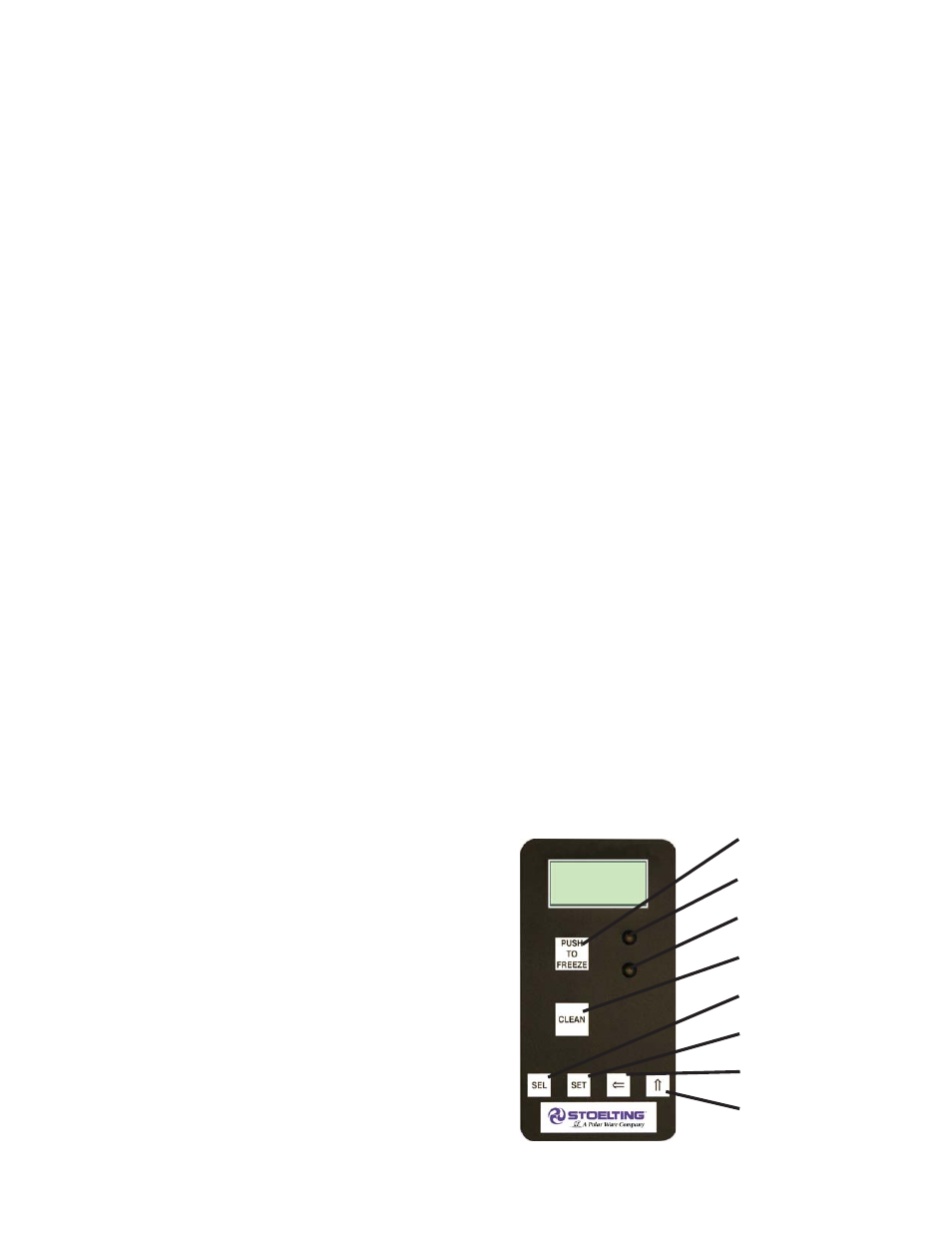
Figure 3-2 IntelliTec Control
Push to Freeze
Green LED
Amber LED
SEL Button
SET Button
Purge/Clean
Button
Up Arrow Button
Left Arrow Button