Page 8, Determining the mounting hardware – Vogels PFW 6851 User Manual
Page 8
Page
8
PFW 6851
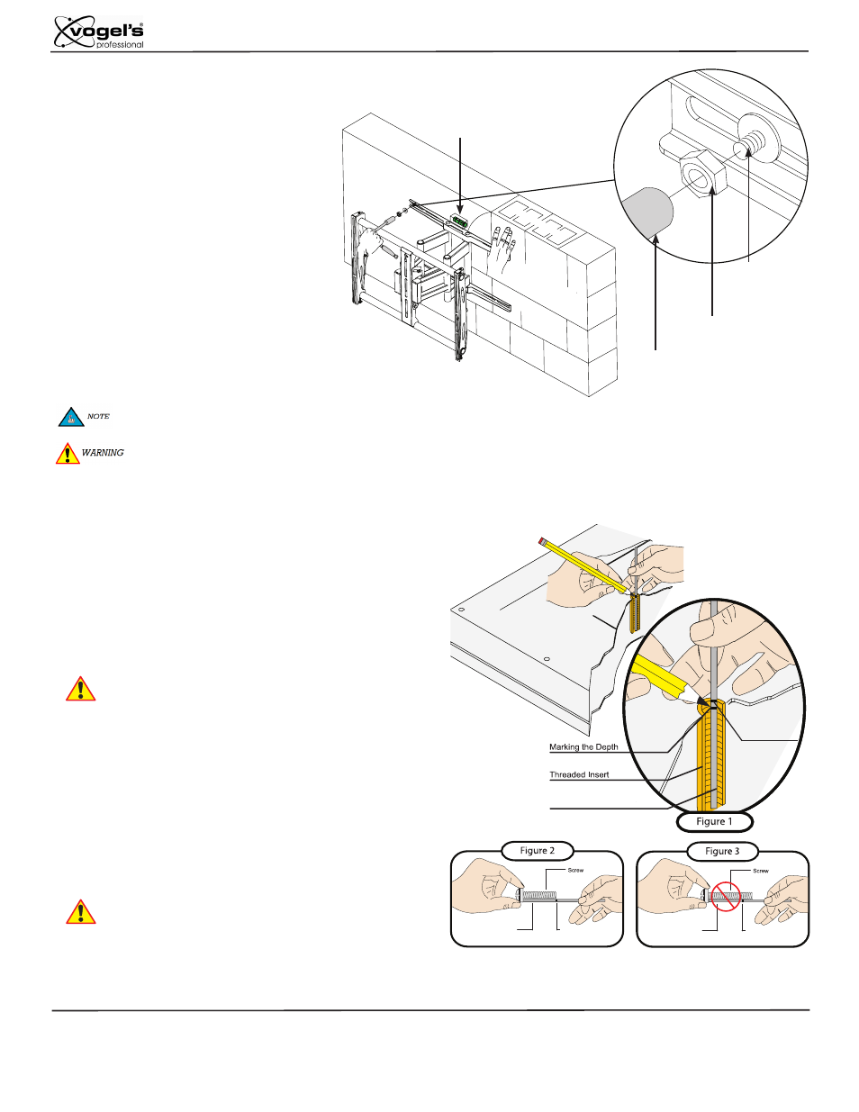
Determining the Mounting Hardware
Step 7. Once all of the anchors are in place, move
the wall bracket into position.
Step 8. Attach the nut onto the threaded shaft that
is protruding from the wall.
Step 9. Re-level the wall plate and tighten all
concrete wedge anchor nuts at this time.
If concrete wedge anchors are not used (as described in these installation instructions) and you decide on other mounting
hardware, please follow the installation instructions as provided with that hardware.
1/2” Socket
Threaded
Shaft
Nut
Level
Do NOT over-tighten the concrete wedge anchors.
Small Straw or Toothpick
Small Straw
or Toothpick
Small Straw
or Toothpick
Marking the 1/8”
Allowance
Depth Plus 1/8” Allowance
Mark
Depth Plus 1/8” Allowance
Mark
n
n
Insert a small straw or toothpick into the threaded inserts found on the
back of the flat panel.
n
o
Use a pencil to mark the depth of the threaded insert on the small straw or
toothpick.
n
p
Mark the straw or toothpick 1/8” above the depth of the threaded insert, as
shown in Figure 1.
n
q
Insert the small straw or toothpick into the remaining threaded inserts
to compare and verify their depth using the straw or toothpick’s 1/8”
allowance mark.
n
r
Locate the correct diameter screw for the threaded insert.
If the screw you selected is longer than the 1/8” allowance mark on the
small straw or toothpick, as shown in Figure 2 and Figure 3, do not use
this screw. The screw length must not bypass the mark.
n
s
Test each size of the screws provided.
The correct screws should thread easily into the mounting point and not
pull out when tension is applied.
You must account for the bracket, spacers and Griplate™
depths when using the Thread Depth Indicator to measure
the thread depth of your flat panel.