Seiwa SW AP01 User Manual
Page 31
3.1 JUNCTION BOX
The Junction Box should mounted on a vertical surface with the cable entry holes
facing downwards. It should be protected from the weather and be well above the
bilge water level in the vessel. Do not mount it in the engine room or other high-
temperature location. Two further considerations are that the connection sockets be
easily accessible when the lid is removed and that there is a space of at least 50mm
on all four sides to permit air circulation. (The outer case forms a heat sink for the
internal power components). Fix the case using screws through the two mounting
flanges. To open the case, remove the four screws holding the cover flanges to the
base and lift the cover. Before commencing the wiring, isolate the vessel’s power bus
from the power supply. Note that all connections to the Junction Box, except for motor
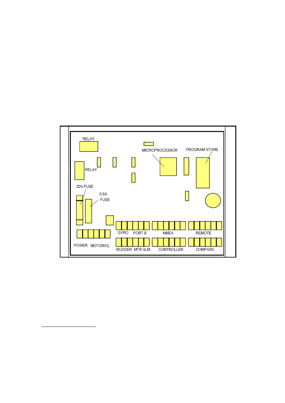
and power, are made to removable plugs. Figs 3.1 show the location of the sockets
and principal components for the S81.01
Figure 3.1 Layout of S81.01Junction Box components
and connectors.
The quality of the power supply to the Junction Box is important for reliable operation.
Large voltage spikes caused by switching other electrical gear on the vessel, or the
supply voltage moving outside the specified limits can cause the system to reset.
These problems are reduced by using heavy wiring and connecting the system to a
point as close as practical to the main batteries.
30