Pfannenberg PAI User Manual
Page 11
11 / 46
685 408 005
CAUTION!
Chips may damage the switch cabinet.
If the required cutouts are only made in the switch cabinet
just before mounting of the air/air heat exchanger, make
sure that swarf is not allowed to enter the device hood by
using a cover sheet, for example.
Hint
To facilitate installation with heavy units, M8 lifting eyes can be
screwed into the upper fixing on the equipment housing. Simple
„one man installation“ is thereby possible.
8.2 Installation of side-mounted, bolt-on air/air heat
exchanger PAS
The mounting surface of the switch cabinet is to be provided with
cutout(s) and holes for air ventilation openings and for securing
the unit according to the accompanying sheet.
The drawing on the accompanying sheet also shows the location
of the electrical connections and ventilation openings.
1) Make cutout(s) and drillings for the air/air heat exchanger, if not
already provided in the switch cabinet (see drawing on
accompanying sheet).Remove burrs from the cut edges.
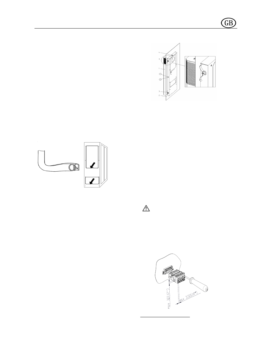
2) Position the profile seal around the rim of the cutout(s). Position
the seal so that the impact ends are facing downwards.
1)
Screw the two threaded studs included in the component
pack into the upper fixing point of the air/air heat exchanger.
Suspend the unit from outside onto the switch cabinet using
the threaded studs.
4) Use the screws, nuts and washers included in the component
pack to secure the air/air heat exchanger on the inner side of the
switch cabinet. Tighten up fixings so that the seal is compressed
to a thickness of 2 mm.
5) Clamp the cable as shown in the connection diagram (see back
of unit) to the plug (component pack) and connect to the unit.
- conductor size: 0,5 – 2,5mm² or AWG20 - AWG14 (In the
selection of cable size, the relevant regulations must be
observed!)
6) Connect the unit to the electrical supply (see section 8.4).
8.3 Installation of built-in air/air heat exchanger PAI
The mounting surface of the switch cabinet is to be provided with
a rectangular cutout as shown on the accompanying sheet. The
drawing on the accompanying sheet shows the location of the
ventilation openings after mounting the unit as seen from the
inside of the switch cabinet.
1) Make cutout for the air/air heat exchanger, if not already
provided in the switch cabinet (see drawing on accompanying
sheet).Remove burrs from the cut edges:
2) From the outside, insert the air/air heat exchanger (Pos. 1) into
the cutout and push through until the unit seal engages with the
switch cabinet (Pos. 2). Close the snap-fasteners (Pos.4) with
an audible click from the unit or upper side and secure the unit
against falling out.
1 air/air heat exchanger
2 Switch cabinet wall or door
3 Securing spring
4 Snap fastener
3) On the inside of switch cabinet, make sure that the securing
springs (Pos.3) supplied in the component pack rest in their
locations. To do this, compress the springs by hand so that
the securing bracket can be secured in the housing cutout.
In switch cabinets with reinforcing frames, insert the securing
springs in the housing cutouts.
4) Clamp cables in accordance with the connection diagram (see
rear of unit) to the plug-in connectors (enclosed package) and
connect to the unit.
- lead cross-section: 0.5 – 2.5 mm², and/or AWG20 –
AWG14 (for the selection of the cable cross-section
the relevant provisions are to be taken into account).
5) Connect the air/air heat exchanger to the power source (see
section8.4)
8.4 Power connection
CAUTION!
The air/air heat exchanger must be connected to the mains by
means of a disconnecting device with a contact gap of at least 3
mm when switched off.
No temperature control must be series-connected to the cooling
unit feed.
The fuse as indicated on the ID plate must be series-connected as
line protection.
Power connection and repairs, if applicable, may only be carried
out by authorized trained electricians.
Power supply connection (mains):
Both mains voltage and frequency must correspond to the