Error- and warning messages, Despatch settings your settings, Function keys and display – Norgren 33D Electronic Pressure Switches Installation Instructions User Manual
Page 9
9
7503442.99.10.01
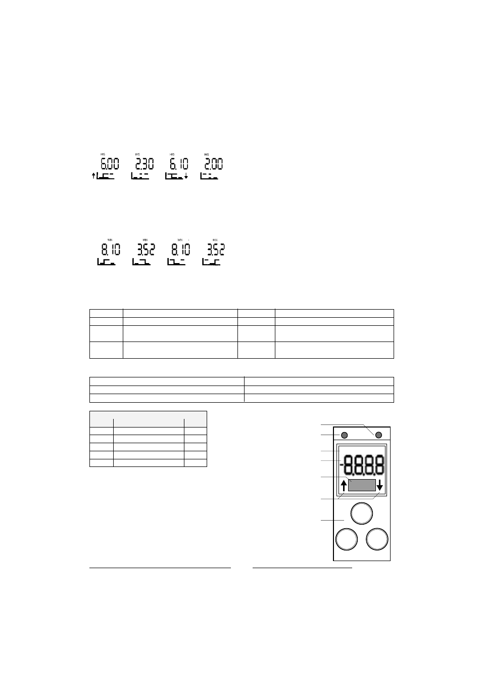
2.2 Hysteresis-MODE:
During the course of the set point setting either the switch-on flank (n.o status) or the switch-off flank (n.c status) will
blink, depending on the operating mode. When setting the hysteresis mode consequently the hysteresis mode will
blink. Depending on the set polarity (n.c. / n.o. see setup) the hysteresis diagram will appear on the display with the
adjustable switching flank blinking.
Picture 2: Switching OUT 1n.o., switching OUT 2 n.c.
2.3 Window MODE:
This operating mode provides the definition of a switching point and a reset point within a pressure range. In case the
prevailing pressure is within this "window”, the switching out will be activated (polarity n.o.) or inactivated (polarity
n.c.)
Picture 3: Switching OUT 1 n.o., switching OUT n.c.
3. Error- and warning messages:
LO VOLT
Supply voltage too low
LO TEMP
Temp. Signal too low or sensor defect
HI PRES
Pressure signal too high or sensor defekt
CALI
Pressure switch not properly calibrated
LO PRES
Sensor defect
ESET
Pressure switch not properly
calibrated
HI TEMP
Temp. Signal too high or sensor defect
ESH1 (2)
SETUP settings OUT 1 (2)
for mode, on/off time not correct
4. Despatch settings
Your settings
– Display bar
– Switching mode Standard n. o.
– Switch on/off delay 0 sec.
▼
▼
SET
OUT1 HYS WIN OUT2
LED Output 2 (optional)
LED Output 1
Indication for Operating MODE
Dot-Matrix for additional informations
Indication during adjusting setpoint and
resetpoint
Keypad with 3 buttons
7-segment display (4 digits)
Function keys and display
Electrical connection M 12 x 1
Pin
Signal
Cable
1
+ U
B
brown
2
Out 2 (PNP) / analog 4 to 20 mA white
3
0 Volt
blue
4
Out 1 (PNP)
black
5
PE
grey