V60 series – Norgren V62 Series Directional Control Valves Datasheets User Manual
Page 17
V60 Series
Littleton, CO USA
Phone: 303-794-2611
www.norgren.com
VAL-3-17
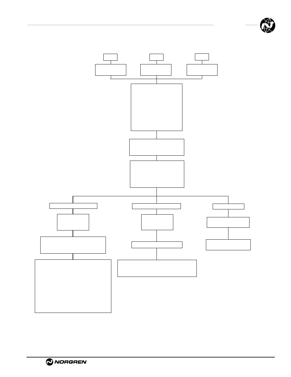
1 = no override
2 = locking
3 = non-locking
V60
V61
V62
P = 1/8" NPT
A= 1/8" ISO G
R = 1/4" NPT
B = 1/4" ISO G
S = 3/8" NPT
C= 3/8" ISO G
3 = 3/2 NO
4 = 3/2 NC
5 = 5/2
6 = 5/3 APB
7 = 5/3 COE
8 = 5/3 COP
A = 2 x 3/2 NC, NC
B = 2 x 3/2 NO, NO
C = 2 x 3/2 NO, NC
1 = Solenoid Pilot, internal
2 = Solenoid Pilot, external
D = Air Pilot
1 = Solenoid Pilot, internal
2 = Solenoid Pilot, external
3 = Air Spring Return
7 = Spring Return
D = Air Pilot
AA = Standard Solenoid
DC = Twin Pilot Solenoid
AX = Air Pilot
1 = no override
2 = locking
3 = non-locking
5 = M5 air pilot ports
P = 1/8" NPT
12J = 12 Vdc 16J = 48 Vac
13J = 24 Vdc 18J = 120 Vac
14J = 24 Vac 19J = 240 Vac
13A = 24 Vdc twin pilot
020 = double air pilot
090 = single air pilot
A = No connector
B = Cable grip 0-240 Vac/Vdc
C = 6 ft molded cable, 0-240 Vac/Vdc
H = Cable grip w/indicator light 24Vdc
J = Cable grip w/indicator light 120Vac
Z = 1/2" Conduit 0-240 Vac/Vdc
5 = 6 ft molded cable w/indicator light,
surge suppression, 24Vac/Vdc
6 = 6 ft molded cable w/indicator light,
surge suppression, 120Vac
A = no connector
Y = 4–pin cable grip 0-240Vac/Vdc
X = 4–pin molded cable 0-240Vac/Vdc
V 6 0 A 5 1 7 A – A 3 1 3 J B