F-series plus cylinders – Norgren F-Series Plus Cylinders User Manual
Page 3
N/US- 5.4.251.03
F-Series Plus Cylinders
11/09
Our policy is one of continued research and development. We therefore reserve the right to amend,
without notice, the specifications given in this document.
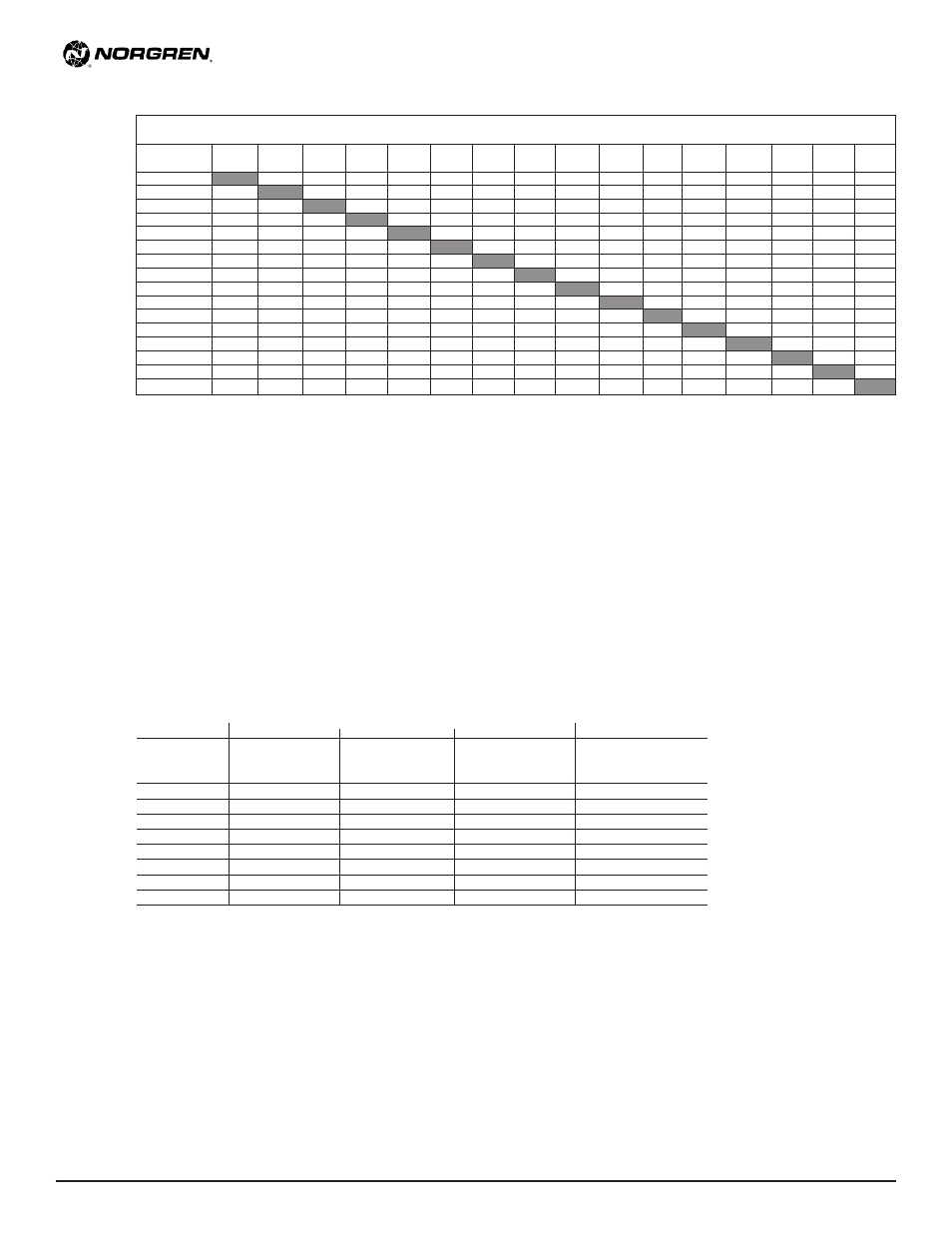
Option Combination Availability Chart
= Available as an option
X = Not Available
M1,M2,
FT(__)
HD
HT
LF
M3,M4
PL(__)
PR
PS
RW
RX(__)
SF
TM(__)
TX(__)
UB
UC
UH
FT(__)
X
X
X
HD
HT
X
X
X
LF
X
M1,M2, M3,M4
PL(__)
PR
X
X
X
PS
RW
X
RX(__)
SF
TM(__)
X
X
TX(__)
X
X
UB
X
X
X
UC
X
X
X
UH
X
X
X
Force Factor Data
Bore
Code
Force Factor (Area)
Extend
Retract
9/16"
(056)
0.25
0.20
3/4"
(075)
0.44
0.36
1-1/16"
(106)
0.89
0.69
1-1/2"
(150)
1.77
1.46
2"
(200)
3.14
2.70
2-1/2"
(250)
4.91
4.47
3"
(300)
7.07
6.47
4"
(400)
12.56
11.77
Force Output Formula
Cylinder Output Force = Force Factor (area) x Air Line
Pressure (psi)
Ex: 1-1/16 bore cylinder operating at 80 psi:
Force exerted on the extend:
0.89 x 80 = 71.2 lbs.
Force exerted on the retract: 0.69 x 80 = 55.2 lbs.
Approximate Cylinder Weights (lbs.)
FP
FPD
FPR, FPC
Nose Mount Option
Bore
Code
Base
Adder per
Base
Adder per
Base
Adder per
Adder to Base Weight
1/8"
1/8"
1/8"
stroke
stroke
stroke
9/16"
(056)
0.075
0.005
0.081
0.009
0.094
0.005
0.006
3/4"
(075)
0.119
0.006
0.131
0.013
0.138
0.006
0.013
1-1/16" (106)
0.306
0.019
0.363
0.025
0.331
0.019
0.069
1-1/2"
(150)
0.600
0.025
0.700
0.038
0.669
0.025
0.113
2"
(200)
0.813
0.031
0.950
0.044
0.894
0.031
0.169
2-1/2"
(250)
1.400
0.038
1.750
0.050
1.581
0.038
0.194
3"
(300)
1.806
0.050
2.375
0.069
2.050
0.050
0.219
4"
(400)
3.481
0.063
4.488
0.081
3.881
0.063
0.369