Standard, Wiring diagram for m12 male connector – Norgren PRA/882000/M IVAC Cleanline cylinder User Manual
Page 8
PRA/882000/M
N/us 1.5.260.08
4/13
Our policy is one of continued research and development. We therefore reserve the right to amend,
without notice, the specifications given in this document.
© Norgren, Inc. 2013
Mountings
Front or rear stud mounting A
Conforms to ISO 15552, type MX1
Piston rod swivel AK
B 1
L 2
L
F
KK
4∞
4∞
KK
3
2
4
1
Ø
BB
DD
TG
lb. (kg)
Model (A)
32/40
0.67
M6
1.28/1.5
0.04
QM/8032/35
(17.0)
(32.5/38)
(0.02)
50/63
0.91
M8
1.83/2.22
0.11
QM/8050/35
(23.0)
(46.5/56.5)
(0.05)
80/100
1.10
M10
2.83/3.5
0.18
QM/8080/35
(28.0)
(72/89)
(0.08)
Standard
Ø
KK
B1
F
L
L2
1
2
3
4 lb. (kg) Model (AK)
32
M10x1.25 0.20 1.02
2.87
0.79 0.75
0.47
0.67
1.18
0.44
QM/8025/38
(5)
(26)
(73)
(20) (19)
(12)
(17)
(30)
(0.2)
40
M12x1.25 0.24 1.02
3.03
0.94 0.75
0.47
0.75
1.18
0.44
QM/8040/38
(6)
(26)
(77)
(24) (19)
(12)
(19)
(30)
(0.2)
50/63
M16x1.5
0.31 1.34
4.17
1.26 1.18
0.75
0.94
1.65
1.43
QM/8050/38
(8)
(34)
(106) (32) (30)
(19)
(24)
(42)
(0.65)
80/100 M20x1.5
0.39 1.65
4.80
1.57 1.18
0.75
1.18
1.65
1.58
QM/8080/38
(10)
(42)
(122) (40) (30)
(19)
(30)
(42)
(0.72)
Standard
Valves
Wiring diagram for connector cable
M/P74581/., M/P74582/.
Pin 1
Not used
White
Pin 2
Solenoid 2 (instroke)
Brown
Pin 3
0 V
Green
Pin 4
Solenoid 1 (outstroke)
Yellow
Switches
Wiring diagram for connector cable
M/P73200/.
Pin 5
+ 24 V d.c.
Grey
Pin 6
Switch 2 (rear end cover)
Pink
Pin 7
0 V
Blue
Pin 8
Switch 1 (front end cover)
Red
Switches
Wiring diagram for connector cable
M/P74581/., M/P74582/.
Pin 5
+ 24 V d.c.
Grey
Pin 6
Switch 2 (rear end cover)
Pink
Pin 7
0 V
Blue
Pin 8
Switch 1 (front end cover)
Red
Wiring diagram for M12 male connector
1
8
4
2
3
7
6
5
1
8
4
2
3
7
6
5
BB
DD
TG
TG
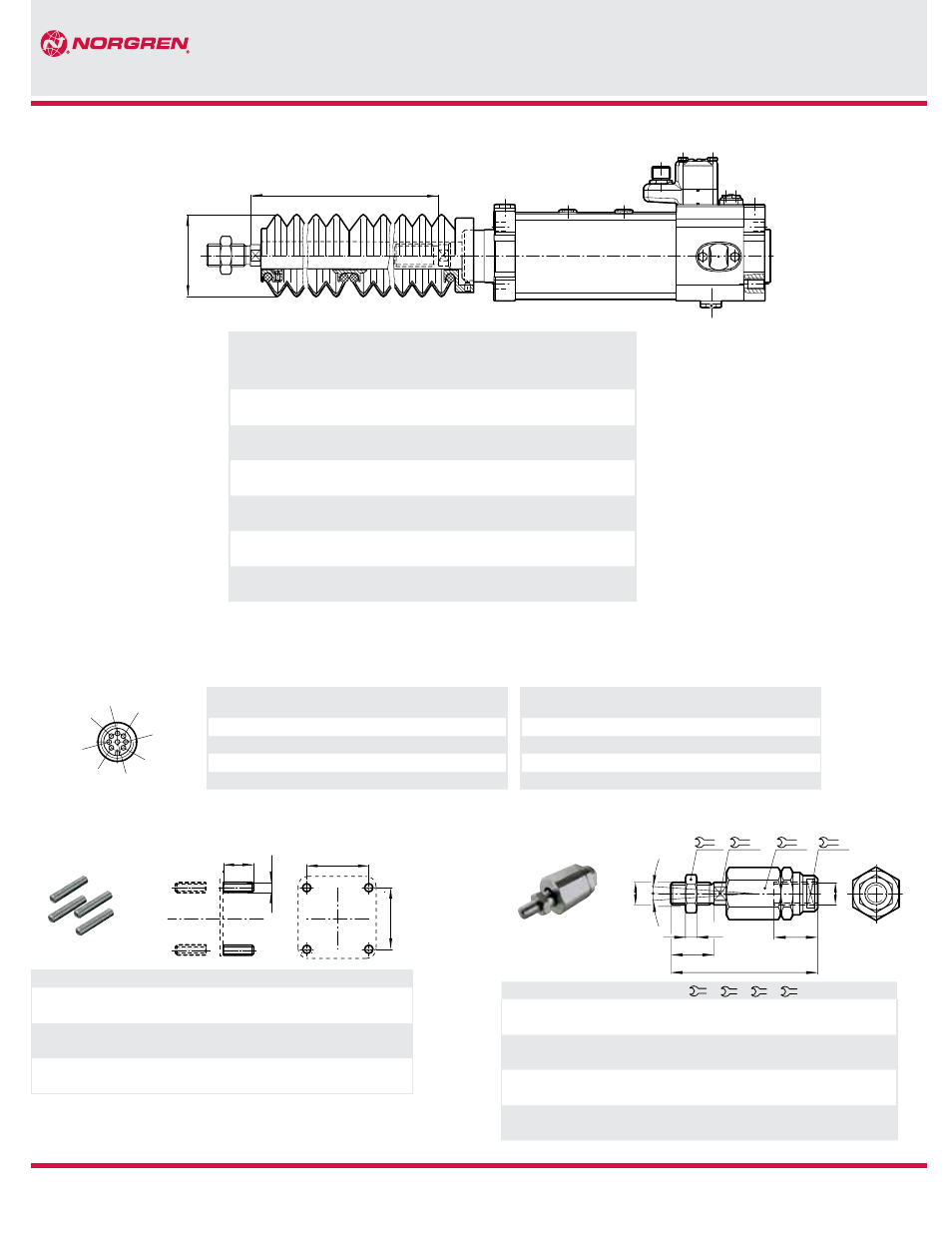
øA
B
Cyl.
Ш
Ш A
Stroke max
per bellow
Piston rod extention B
for first for further
bellow bellows
Model
32
1.57
2.36
1.18
0.98
P#A/882032/MG+/M./*
(40)
(60)
(30)
(25)
40
2.48
5.71
1.97
1.26
P#A/882040/MG+/M./*
(63)
(145)
(50)
(32)
50
2.48
5.71
1.57
1.26
P#A/882050/MG+/M./*
(63)
(145)
(40)
(32)
63
2.48
5.71
1.57
1.26
P#A/882063/MG+/M./*
(63)
(145)
(40)
(32)
80
3.15
9.84
1.97
1.77
P#A/882080/MG+/M./*
(80)
(250)
(50)
(45)
100
3.15
9.81
1.97
1.77
P#A/882100/MG+/M./*
(80)
(250)
(50)
(45)
* Standard stroke length
# Piston rod material
+ Valve function
P*A/882000/MG*/M*/* Cylinder with piston rod bellow