FMI ICST-01 User Manual
Page 5
IN-ICST-01-07 5
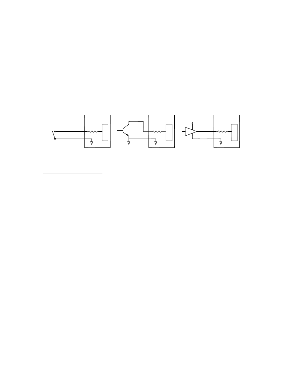
NOTES ON TTL LOGIC: For interface to PLC or other type of control.
TTL (Logic High)
≥ 2.0 Vdc
TTL ( logic Low)
≤ 0.6 Vdc
Vin ( Absolute Maximum) = 5Vdc
Vin ( Absolute Mininum) = 0.0Vdc
Vin ( Logical High) =
≥ 3.5 Vdc.
Vin ( Logical Low) =
≤ 1.0 Vdc.
ACCEPTABLE INPUTS
DRY CONTACT
5 Vdc
TTL or CMOS LOGIC
OPEN COLLECTOR
(OPEN DRAIN)
4. Wiring Specifications
4.1 P/N ICST-01
Wiring for terminal strip marked J12:
Number 1 is the B bar phase to the motor.
Number 2 is the B phase to the motor. Note: See section 3 system
Number 3 is the A bar phase to the motor installation for motor wiring.
Number 4 is the A phase to the motor.
Number 5 is the Black wire from the sensor.
Number 6 is the Red wire from the sensor.
Number 7 is the Green wire from the sensor.
Number 8 is the Blue wire from the sensor.
Number 9 is the White wire from the sensor.
Number 10 is the Brown wire for Relay 1 (- side activated).
Number 11 is the Orange wire for Relay 2 (- side activated).
Number 12 is the 2 Red wires (+24 Vdc) for Relay power.
Wiring for terminal strip marked J11:
Numbers 1 and 2 are Ground, the Lt Blue wire two places.
Number 3 is the Push Button Switch (Activation Switch), the Yellow wire.
Number 4 is the Dip Switch 1 (I/O1), the Black wire.
Number 5 is the Dip Switch 2 (I/O2), the Purple wire.
Number 6 is the Dip Switch 3 (I/O3), the Orange wire.
Number 7 is the Dip Switch 4 (I/O4), the Red wire.
Number 8 is the Dip Switch 5 (I/O5, the Gray wire.