Timing diagrams, 1 timing diagram in the case of a cold boot, An186 – Cirrus Logic AN186 User Manual
Page 8
AN186
8
AN186REV1
8. TIMING DIAGRAMS
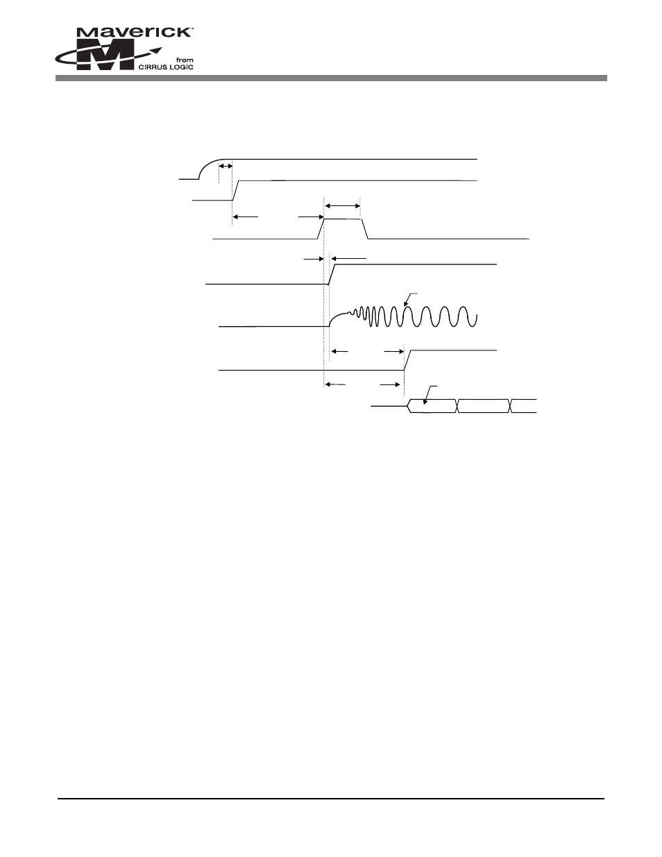
8.1 Timing Diagram in the case of a Cold Boot
Notes: 1. nPOR (active low) should be held low until the power supply reaches its operational voltage to initialize
the EP72/73XX properly, and to allow the RTC to stabilize. Since the power-on reset operates
asynchronously to the system clock, it is not required to wait until the system clock is stabilized.
2. During normal operation (i.e., after the initial power-up) if nPOR is used to reset the EP72/73XX, it
needs to be held low for at least one clock cycle of the selected clock speed (e.g., when running at 13
MHz, the low pulse width needs to be > 77 ns). This is done to guarantee that it will be detected low.
3. The EP72/73XX will not start trying to detect the active going edge of the WAKEUP signal until up to 2
seconds after the power-on reset. If the WAKEUP signal goes HIGH prior to this time delay, it may not
be acknowledged, thus requiring another wakeup signal fulfilling the minimum pulse width.
4. Upon pressing the power-on reset, the configuration bit (CLKENSL) in the SYSCON2 register is reset
to 0, resulting in the RUN/CLKEN output pin programmed as “CLKEN.”
Internal RUN
Instruction fetches
nPOR (input)
See note 1.
OSC/PLL
Stable clock
CLKEN (output)
See note 4
.
2sec min
See note
3
(
62-125us
)
(
125-250ms
)
Power
Supply
125us min. width
Wakeup
delay
100us min. width
WAKEUP
See note 3
2 sec max.
delay
Figure 3. Timing Diagram for the Case of a Cold Boot