Wakeup and nureset caveat, An186 – Cirrus Logic AN186 User Manual
Page 7
AN186
AN186REV1
7
7. WAKEUP AND nURESET CAVEAT
When the WAKEUP signal is used to exit the Standby State, nURESET must be held in its inactive state. During the period of
time between when the WAKEUP signal becomes active and the EP72/73XX device completely enters the Operating State,
nURESET must remain inactive. If nURESET becomes active during this period of time, the device may lock up, and the only
recovering mechanism is to perform a complete reset. This will have to be accomplished by using the nPOR signal. It is very
easy to avoid this potential overlap between these two signals.
OPTION #1:
Tie nURESET to V
dd.
This approach is the simplest.
However, if the functionality that nURESET can provide is desired, then refer to Option #2.
OPTION #2:
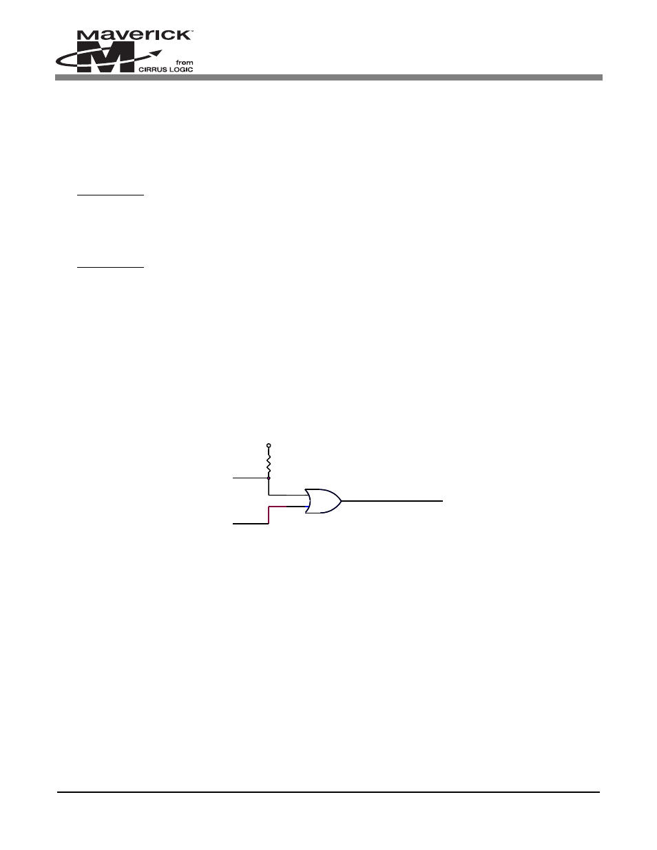
Implement a circuit that keeps nURESET inactive during the prescribed period of time. (The period of time between when
the WAKEUP signal becomes active and the EP72/73XX device completely enters the Operating State.) A very simple
circuit will fulfill this requirement. See
.
This is how it works:
Upon power-up, the output of the OR gate is forced high, thus forcing nURESET to be inactive. It is forced high because the
GPIO signal is configured as an input upon power-up (if using one of Port A, B, or E’s pins), or it is forced high upon power-
up if it is one of Port D’s pins. Therefore, any activity on the actual “User Reset” signal, which could be from a pushbutton, will
have no effect. After the device has entered the Operating State, the initialization code can configure the used GPIO pin so that
it drives its output low. This will now allow the “User Reset” signal to force the nURESET signal to be driven low (i.e., active).
User Reset
nURESET
R1
100k
U1
OR2
1
2
3
VCC
Unused GPIO
Figure 2. Example Circuit for Keeping nURESET Inactive during Prescribed Period