Introduction, The supported power management states, Figure 1. ep72/73xx power management states – Cirrus Logic AN186 User Manual
Page 3: The deglitcher, Wakeup delays, An186
AN186
AN186REV1
3
1. INTRODUCTION
This application note describes in detail the recommended procedure for applying power to the EP72/73XX device, and how to
transition from the Standby State into the Operating State.
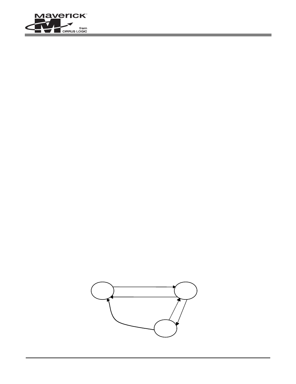
2. THE SUPPORTED POWER MANAGEMENT STATES
The EP72/73XX supports the following Power Management States:
l Operating — The normal program Execution State is the Operating State; this is a full performance State where all of
the clocks and peripherals are enabled.
l Idle — The Idle State is the same as the Operating State with the exception of the CPU clock being halted. An interrupt
will return it back to the Operating State.
l Standby — The Standby State has the lowest power consumption; selecting this state shuts down the main oscillator,
leaving only the Real Time Clock (RTC) and its associated logic powered. When the EP72/73XX is in the Standby State,
the device is basically turned “off.” Only the WAKEUP pin or interrupt source can wake up the device.
See
Figure 1
to see the interactions between the power management states.
Note:
The WAKEUP signal is only used to exit the Standby State, not the Idle State. The only state that the
Standby State can transition to is the Operating State.
3. THE DEGLITCHER
Built into the EP72/73XX are six identical conditioning circuits. They are designed to deglitch the following six signals:
l WAKEUP
l nBATCHG
l nPWRFL
l nURESET
l nMEDCHG
l Low Battery Interrupt (combination of BATOK, nEXTPWR and the internal RUN signal).
For any of the above signals to become active internal to the EP72/73XX, they must first be deglitched. Each deglitcher is simply
two D Flip Flops in series configured so that the input signal must be held active (HIGH) for a minimum of two clock edges.
The clock source is derived from the RTC. It is ½ the RTC frequency (i.e., ½ of 32.768 kHz = 16.384 kHz). The deglitcher
performs two tasks:
1)
No input signal will pass through it, unless it is held active for at least two clock edges.
2)
It guarantees that the output signal from the deglitcher will be active for a minimum of ~ 62us (i.e., 1/16.384 kHz).
4. WAKEUP DELAYS
The EP72/73XX device has several different time delays that may occur when powering up and/or exiting the Standby State.
The sections below describe them all.
Interrupt or Rising Wakeup
O
PERATING
I
DLE
S
TANDBY
nPor, Low Battery,
or User Reset
I
NTERRUPT
Write to Standby Location,
Low Battery, or User Reset
Write to Halt
Location
Figure 1. EP72/73XX Power Management States