Capacitor size on the reference pin (filt+), Conclusion, An249 – Cirrus Logic AN249 User Manual
Page 9: F capacitor in parallel with a 1
AN249
9
8. Capacitor Size on the Reference Pin (FILT+)
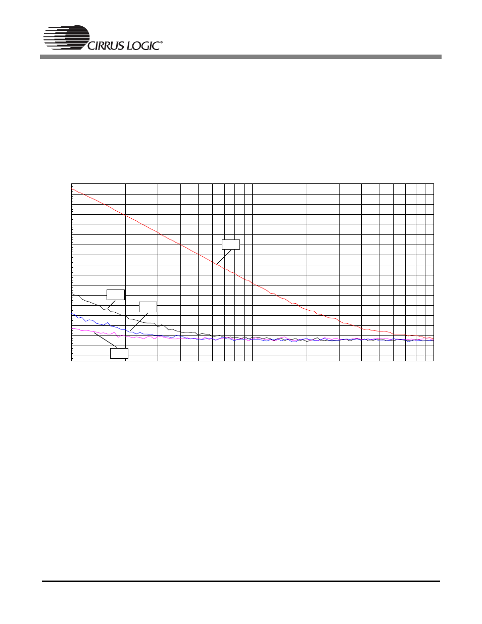
The CS5340 and CS5333 require external capacitance on the internal reference voltage pin. For the
CS5333, the internal reference voltage is output on FILT+ (pin 11). On the CS5340, the FILT+ reference
voltage is output on pin 15. The size of the decoupling capacitor on this reference pin will affect the low
frequency distortion performance. The recommended solution for the CS5333 is a 1
µ
F capacitor between
the FILT+ pin and analog ground. The recommended solution for the CS5340 is to use a 0.1
µ
F capacitor
in parallel with a 1
µ
F capacitor for cost sensitive applications. See Figure 7 which illustrates the typical
low frequency distortion performance of the CS5340 with different size capacitors on the FILT+ reference
pin (pin 15). This plot was taken implementing the recommended input filter shown in Figure 4.
Figure 7. CS5340 THD+N versus Frequency
9. Conclusion
The CS5340 is the recommended replacement for the CS5333, offering higher performance and 192 kHz
output sample rate capability. Special considerations must be made when upgrading designs to use the
CS5340 in place of the CS5333. These considerations include pin compatibility, functional mode selec-
tions, input filter design, and external capacitor requirements on the FILT+ reference pin.
-104
-70
-102
-100
-98
-96
-94
-92
-90
-88
-86
-84
-82
-80
-78
-76
-74
-72
d
B
F
S
10
1k
20
50
100
200
500
Hz
1 uF
10 uF
22 uF
47 uF