An249 – Cirrus Logic AN249 User Manual
Page 2
AN249
2
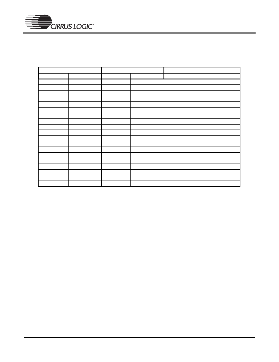
The CS5333 and CS5340 are both available in a 16-pin TSSOP package. As can be seen from Table 2,
all but three pins correlate directly in terms of functionality. These three pins account for a difference in
operational mode selection and a separate voltage supply pin for the CS5340 digital core.
Table 2. Pin Compatibility Between the CS5333 and CS5340
CS5333
CS5340
Description
Pin Number
Pin Name
Pin Number
Pin Name
1
VL
3
VL
Logic Power
2
MCLK
2
MCLK
Master Clock
3
SCLK
7
SCLK
Serial Clock
4
SDATA
4
SDOUT
Serial Data
5
VA
13
VA
Analog Power
6
GND
5
GND
Ground Reference
7
LRCK
8
LRCK
Left/Right Clock
8
DIV
-
-
Speed Mode Select/MCLK Divider
9
DIF
-
-
Digital Interface Format Select
10
TST
-
-
Test Pin
11
FILT+
15
FILT+
Voltage Reference
12
REF_GND
14
REF_GND
Ground Reference
13
AINR
12
AINR
Right Channel Analog Input
14
AINL
10
AINL
Left Channel Analog Input
15
VQ
11
VQ
Quiescent Voltage Reference
16
RST
9
RST
Reset
1
M0
Mode Selection
6
VD
Digital Power
16
M1
Mode Selection
- CobraNet (147 pages)
- CS4961xx (54 pages)
- CS150x (8 pages)
- CS1501 (16 pages)
- CS1601 (2 pages)
- CS1601 (16 pages)
- CS1610 (16 pages)
- CRD1610-8W (24 pages)
- CRD1611-8W (25 pages)
- CDB1610-8W (21 pages)
- CS1610A (18 pages)
- CDB1611-8W (21 pages)
- CDB1610A-8W (21 pages)
- CDB1611A-8W (21 pages)
- CRD1610A-8W (24 pages)
- CRD1611A-8W (25 pages)
- CS1615 (16 pages)
- AN403 (15 pages)
- AN401 (14 pages)
- AN400 (15 pages)
- AN375 (27 pages)
- AN376 (9 pages)
- CRD1615-8W (22 pages)
- CRD1616-8W (23 pages)
- AN402 (14 pages)
- AN404 (15 pages)
- CRD1615A-8W (21 pages)
- CS1615A (16 pages)
- CS1630 (56 pages)
- AN374 (35 pages)
- AN368 (80 pages)
- CRD1630-10W (24 pages)
- CRD1631-10W (25 pages)
- CS1680 (16 pages)
- AN405 (13 pages)
- AN379 (31 pages)
- CRD1680-7W (31 pages)
- AN335 (10 pages)
- AN334 (6 pages)
- AN312 (14 pages)
- AN Integrating CobraNet into Audio Products (16 pages)
- CobraNet Audio Routing Primer (9 pages)
- Bundle Assignments in CobraNet Systems (3 pages)
- CS2300-01 (3 pages)
- CS2000-CP (38 pages)