An249 – Cirrus Logic AN249 User Manual
Page 4
AN249
4
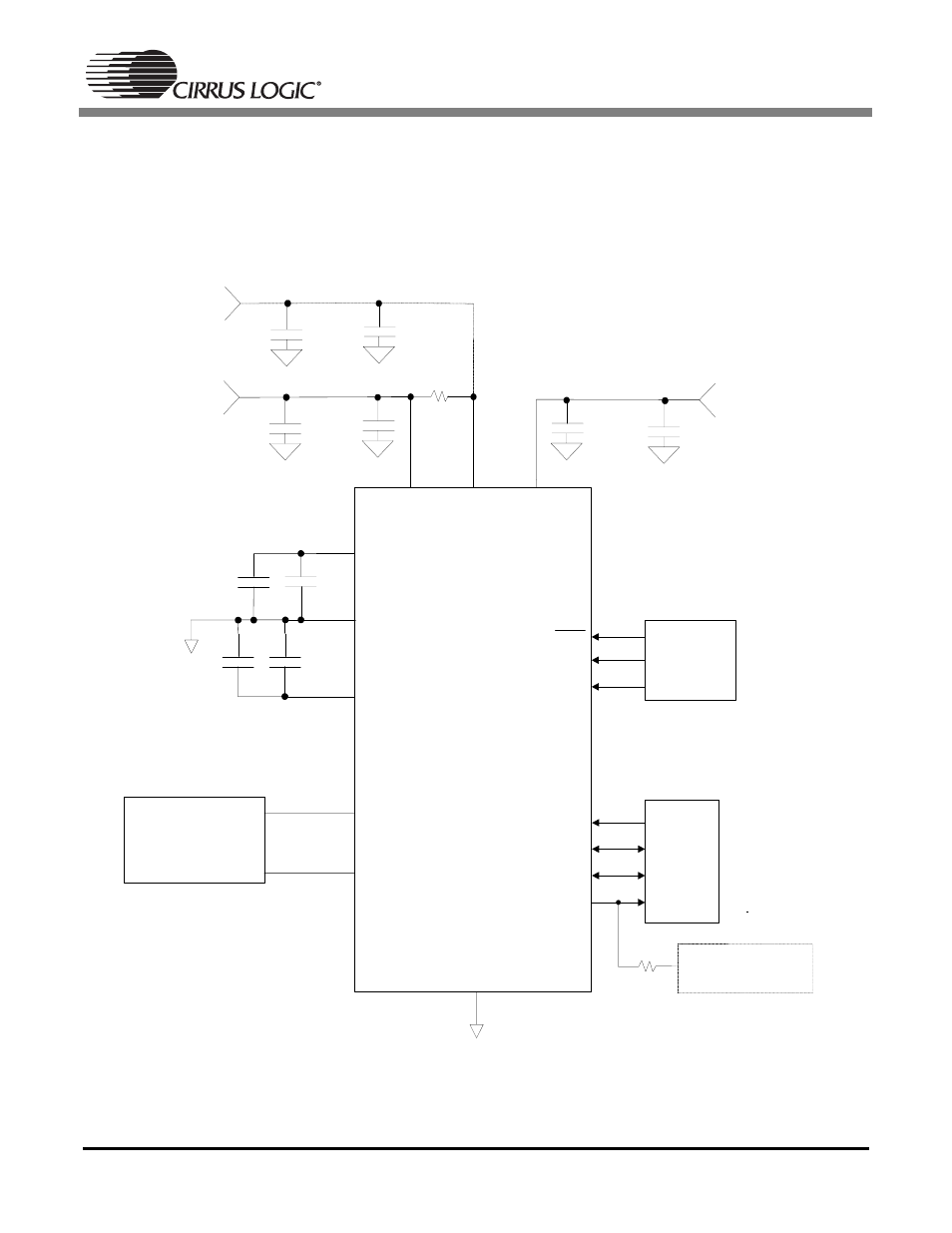
The CS5340 has separate power supply pins for the analog and digital cores. The analog section is pow-
ered from the VA supply and the digital section is powered off of the VD supply. Both of these supply pins
can be powered from the same external source with a small series resistor between them for noise isola-
tion. Both the analog and digital cores can operate independently from 3.3 V to 5.0 V. The VL pin of the
CS5340 supplies the digital interface logic, supports a wide operating range from 1.8 V to 5.0 V, and can
be powered independently from the VA and VD power supplies.
Figure 2. CS5340 Typical Connection Diagram
VA
CS5340
AINL
AINR
GND
Analog Input Filter
Figure 4
FILT+
REF_GND
VQ
1.8 V to 5.0 V
+
3.3 V to 5.0 V
1 µF
1 µ F
VL
0.1 µF
+
1 µF
RST
M1
M0
Mode
Configuration
MCLK
LRCK
SCLK
Digital
Audio
Source
SDOUT
10k Ω
Connect to:
• VL for I2S
• GND for LJ
1
2
3
4
13
5
7
8
9
15
14
12
16
10
11
VD
5.1Ω
+
1 µF
0.1 µF
3.3 V to 5.0 V
*
6
1
µ F
0.1 µF
0.1 µF
0.1 µF
* Resistor may only be
used if VD is derived from
VA. If used, do not drive
any other logic from VD.