Input filter topology, An249 – Cirrus Logic AN249 User Manual
Page 6
AN249
6
7. Input Filter Topology
Both the CS5333 and CS5340 implement a single-ended input architecture. Due to differences in the input
sampling topologies within the converters, the input filter requirements are different between these two
devices.
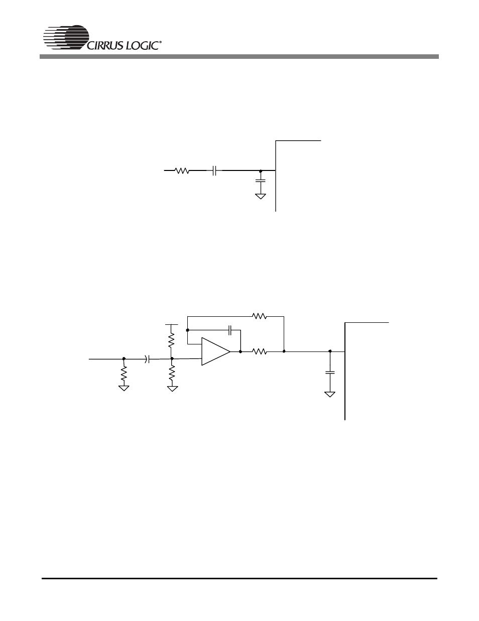
A suggested input filter topology for the CS5333 is shown in Figure 3. This input network consists of an
AC-coupling capacitor along with a single-pole lowpass filter.
Figure 3. CS5333 Input Filter
The CS5333 will self-bias the analog input node to the optimal bias point (half of VA). The CS5333 imple-
ments an internal buffer on the analog input, reducing the amount of switching current on the input sam-
pling node. This reduction in switching current makes the CS5333 less sensitive to series resistance on
the analog input lines.
A suggested input filter topology for the CS5340 is shown in Figure 4.
Figure 4. CS5340 Input Filter
This filter topology implements an external resistor-divider circuit to bias the output of the amplifier to the
optimal bias point (half of VA). Due to the internal architecture, the CS5340 requires low impedance on
the analog input lines. The topology shown in Figure 4 provides a sub-ohm input source impedance into
the CS5340 and isolates the input to the amplifier. For more information on this input filter topology, please
refer to the Application Note AN241.
A passive input filter can be used with the CS5340, however, the full analog performance of the CS5340
will not be realized. Figure 5 illustrates a unity gain, passive input filter solution and the resulting distortion
performance. Please note that in this case the dynamic range performance of the CS5340 will not be lim-
ited by the input filter; only the distortion performance is affected.
AINx
0.47 uF
CS5333
150
Ω
0.01 uF
C0G
AINx
-
+
470 pF
C0G
CS5340
634
Ω
91
Ω
2200 pF
C0G
4.7
µF
100 k
Ω
100 k
Ω
100 k
Ω
V A