Master/slave and speed mode selection, 1 cs5333, 2 cs5340 – Cirrus Logic AN249 User Manual
Page 5: Digital interface format select, System clocking, An249
AN249
5
4. Master/Slave and Speed Mode Selection
4.1
CS5333
In the CS5333, the selection for Master or Slave mode operation is determined by a resistor pull-up/pull-
down on the SDATA pin (pin 4), as noted in Figure 1. If operating in Master mode, the Speed mode is
selected by the DIV pin (pin 8). If DIV is resistively pulled low, the CS5333 will enter into Base Rate mode
(Fs = 2 kHz to 50 kHz). If DIV is resistively pulled high to VL, the CS5333 will enter into High Rate mode
(Fs = 50 kHz to 100 kHz). If the CS5333 is operating in Slave mode, the Speed mode is auto-detected
and the DIV pin operates as an MCLK divide by two enable.
4.2
CS5340
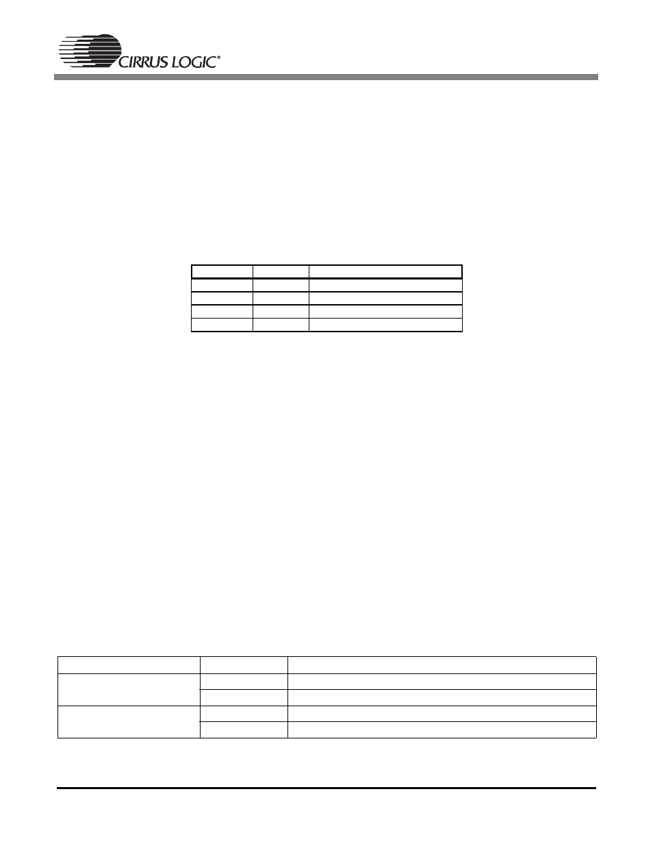
In the CS5340, Master or Slave mode operation and Speed mode is determined by the mode pins, M1
and M0 (pins 16 and 1 respectively), as shown in Table 3.
Table 3. CS5340 Mode Control
Please note that Base Rate mode is synonymous with Single Speed mode, and High Rate mode is syn-
onymous with Double Speed mode.
5. Digital Interface Format Select
5.1
CS5333
The CS5333 supports both Left Justified and I
2
S digital interface formats. The interface is selectable by
the DIF pin (pin 9). If this pin is held at a logic low upon startup, I
2
S interface format will be selected. If
held at a logic high upon startup, Left Justified interface format will be selected.
5.2
CS5340
The CS5340 also supports both Left Justified and I
2
S digital interface formats. The interface is selectable
by a resistor pull-up/pull-down on the SDOUT pin (pin 4). If this pin is resistively pulled low upon startup,
Left Justified interface format will be selected. If this pin is resistively pulled high to VL upon startup, I
2
S
interface format will be selected.
6. System Clocking
The clocking requirements for the CS5333 and CS5340 are the same for Master mode operation. How-
ever, in Slave mode operation the CS5340 only supports a subset of the clocking supported in the
CS5333. The CS5333 supports an MCLK/LRCK ratio of 256x, 384x, 512x, and 768x in Base Rate mode
and 128x, 192x, 256x and 384x in High Rate mode. The CS5340 cannot support ratios of 192x, 384x, or
768x. See Table 4. Due to the auto-speed mode detect circuitry implemented in the CS5340, not all sam-
ple rate ranges are supported in Slave mode. Please refer to the CS5340 datasheet for more information.
Table 4. Supported MCLK/LRCK Ratios, Slave Mode Operation
Device
Speed Mode
Supported MCLK/LRCK Ratios
CS5333
Base Rate
256, 384, 512, 768
High Rate
128, 192, 256, 384
CS5340
Single Speed
256, 512
Double Speed
128, 256
M1 (Pin 16) M0 (Pin 1)
Mode
0
0
Master, Single Speed Mode
0
1
Master, Double Speed Mode
1
0
Master, Quad Speed Mode
1
1
Slave, All Speed Modes