Typical connection diagrams, An249, Cs5333 – Cirrus Logic AN249 User Manual
Page 3
AN249
3
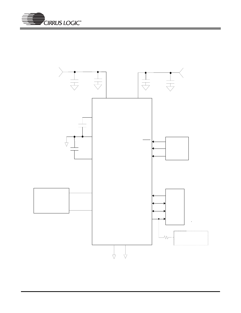
3. Typical Connection Diagrams
Figures 1 and 2 illustrate the typical connection diagram for the CS5333 and CS5340 respectively. The
analog and digital core of the CS5333 are powered from VA, which can be set from 1.8 V to 3.3 V. The
VL supply pin powers the digital interface logic from 1.8 V to 3.3 V and can be set independently from VA.
Figure 1. CS5333 Typical Connection Diagram
VA
CS5333
AINL
AINR
GND
TST
Analog Input Filter
Figure 3
FILT+
REF_GND
VQ
1.8 V to 3.3 V
+
1.8 V to 3.3 V
1 µF
1 µ F
1
µ F
0.1 µF
VL
0.1 µF
+
1 µF
RST
DIF
DIV
Mode
Configuration
MCLK
LRCK
SCLK
Digital
Audio
Source
SDATA
47k Ω Connect to:
• VL for Master Mode
• GND for Slave Mode
1
2
3
4
5
6
7
8
9
10
11
12
13
16
14
15
See also other documents in the category Cirrus Logic Hardware:
- CobraNet (147 pages)
- CS4961xx (54 pages)
- CS150x (8 pages)
- CS1501 (16 pages)
- CS1601 (2 pages)
- CS1601 (16 pages)
- CS1610 (16 pages)
- CRD1610-8W (24 pages)
- CRD1611-8W (25 pages)
- CDB1610-8W (21 pages)
- CS1610A (18 pages)
- CDB1611-8W (21 pages)
- CDB1610A-8W (21 pages)
- CDB1611A-8W (21 pages)
- CRD1610A-8W (24 pages)
- CRD1611A-8W (25 pages)
- CS1615 (16 pages)
- AN403 (15 pages)
- AN401 (14 pages)
- AN400 (15 pages)
- AN375 (27 pages)
- AN376 (9 pages)
- CRD1615-8W (22 pages)
- CRD1616-8W (23 pages)
- AN402 (14 pages)
- AN404 (15 pages)
- CRD1615A-8W (21 pages)
- CS1615A (16 pages)
- CS1630 (56 pages)
- AN374 (35 pages)
- AN368 (80 pages)
- CRD1630-10W (24 pages)
- CRD1631-10W (25 pages)
- CS1680 (16 pages)
- AN405 (13 pages)
- AN379 (31 pages)
- CRD1680-7W (31 pages)
- AN335 (10 pages)
- AN334 (6 pages)
- AN312 (14 pages)
- AN Integrating CobraNet into Audio Products (16 pages)
- CobraNet Audio Routing Primer (9 pages)
- Bundle Assignments in CobraNet Systems (3 pages)
- CS2300-01 (3 pages)
- CS2000-CP (38 pages)