5 mic 1 & 2, 5 mic 1 & 2 -6 – Cirrus Logic CRD48L10 User Manual
Page 20
6
3.1 S1 Button Control (No LCD)
The S/PDIF receiver is configured to automatically switch between the on-board oscillator and the clock recovered from
an incoming S/PDIF stream.
In the previous diagram, any time a valid S/PDIF stream is presented to the CS8416, the system audio clock will be locked
to the Fs of the incoming stream. The S/PDIF cable should be removed when the on-board oscillator (or TP4) is meant to
master audio clocks.
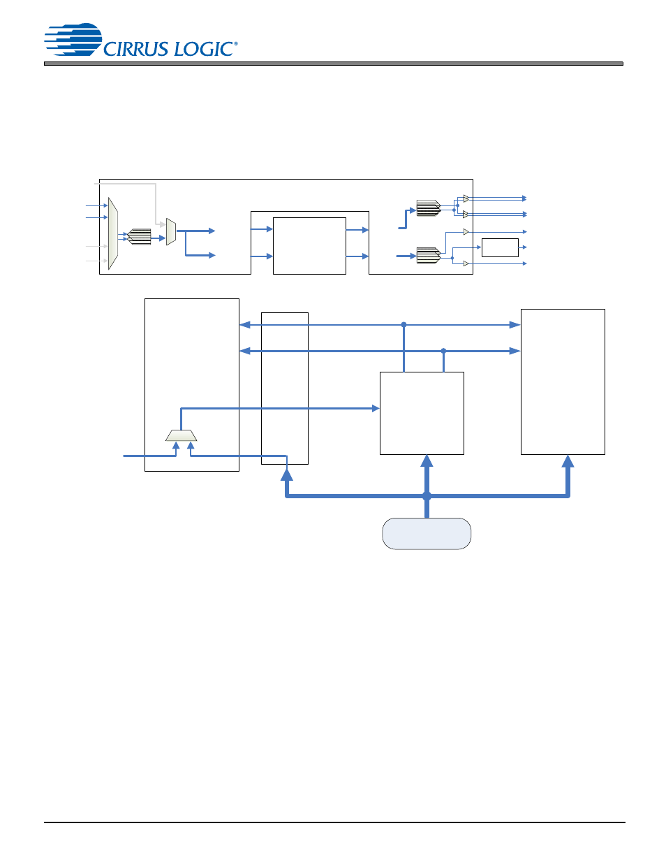
3.1.5
MIC 1 & 2
Figure 3-11. Data Path for MIC 1 & 2 Audio
Figure 3-12. Clocking for MIC 1 & 2 Audio–DSP MCLK Slave
The S/PDIF receiver is configured to automatically switch between the on-board oscillator and the clock recovered from
an incoming S/PDIF stream.
In the previous diagram, any time a valid S/PDIF stream is presented to the CS8416, the system audio clock will be locked
to the Fs of the incoming stream. The S/PDIF cable should be removed when the on-board oscillator (or TP4) is meant to
master audio clocks.
Digital MIC
MIC1
MIC2
Line In (L)
Line In (R)
ASP OUT
XSP OUT
DAI1
DAI2
DAO 1
DAO2
ASP IN
XSP IN
Speakerphone (L)
Speakerphone (R)
AMP
(CS3501 )
EAR
Headphone Outputs (L&R)
Line Outputs (L&R)
(CS42L73)
VSP OUT
VSP IN
SCP
(CS48L10)
ADC
DAC
DAC
Level
Translation
(CS48L10)
(CS42L73)
SPDIF RX
(CS8416 )
CLOCK
MCLK1
MC
L
K
SCLK
LRCLK
SCLK (ASP/XSP)
LRCLK (ASP/XSP)
SCLK
LRCLK
OSCILLATOR
12.288 MHz
Mini Optical RX
Or
1/8" Coax