3 high-impedance digital output, Figure 13. tri-state sclk/lrck, 4 quarter- and half-speed mode – Cirrus Logic CS43L21 User Manual
Page 30: 5 digital interface formats, Figure 14. i²s format, Figure 13.tri-state sclk/lrck figure 14.i²s format, Cs43l21
30
DS723F1
CS43L21
4.4.3
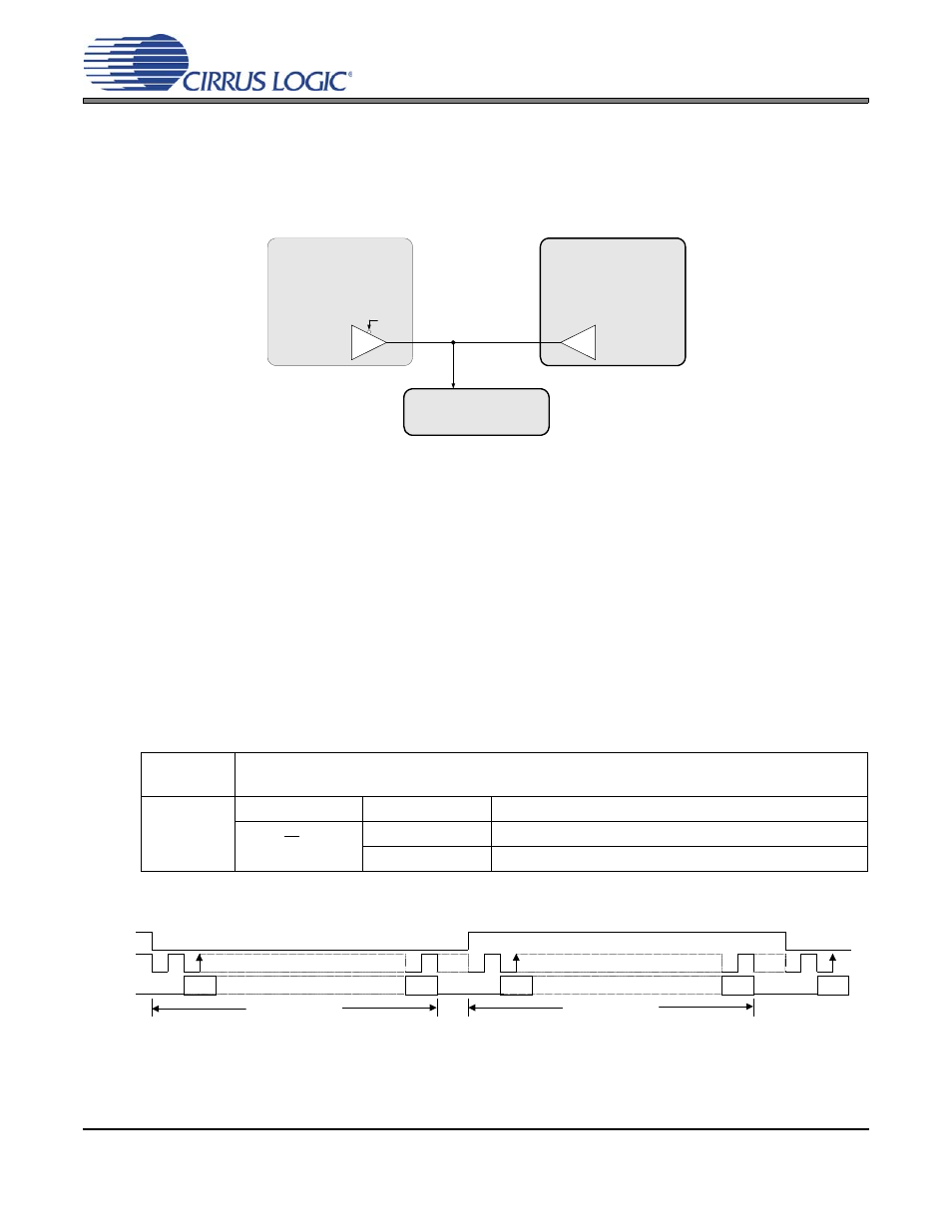
High-Impedance Digital Output
The serial port may be placed on a clock/data bus that allows multiple masters for the SCLK/LRCK I/O
without the need for external buffers. The 3ST_SP bit places the internal buffers for these I/O in a high-
impedance state, allowing another device to transmit clocks without bus contention.
4.4.4
Quarter- and Half-Speed Mode
Quarter-Speed Mode (QSM) and Half-Speed Mode (HSM) allow lower sample rates while maintaining a
relatively flat noise floor in the typical audio band of 20 Hz - 20 kHz. Single-Speed Mode (SSM) will allow
lower frequency sample rates; however, the DAC's noise floor, that normally rises out-of-band, will scale
with the lower sample rate and begin to rise within the audio band. QSM and HSM corrects for most of
this scaling, effectively increasing the dynamic range of the device at lower sample rates, relative to SSM.
4.5
Digital Interface Formats
The serial port operates in standard I²S, Left-Justified or Right-Justified digital interface formats with varying
bit depths from 16 to 24. Data is clocked into the DAC on the rising edge of SCLK.
illustrate
the general structure of each format. Refer to
“Switching Specifications - Serial Port” on page 16
for exact
timing relationship between clocks and data.
Software
Control:
“Interface Control (Address 04h)” on page 42
Hardware
Control:
Pin
Setting
Selection
“I²S/LJ” pin 3
LO
Left-Justified Interface
HI
I²S Interface
CS43L21
Transmitting Device #1
Transmitting Device #2
Receiving Device
3ST_SP
SCLK/LRCK
Figure 13. Tri-State SCLK/LRCK
LRCK
SCLK
M S B
L S B
M S B
L S B
AOUTA
L e ft C h a n n e l
R i g h t C h a n n el
SDIN
AOUTB
MSB
Figure 14. I²S Format