Cirrus Logic CS43122 User Manual
Advance product information, Features, Description
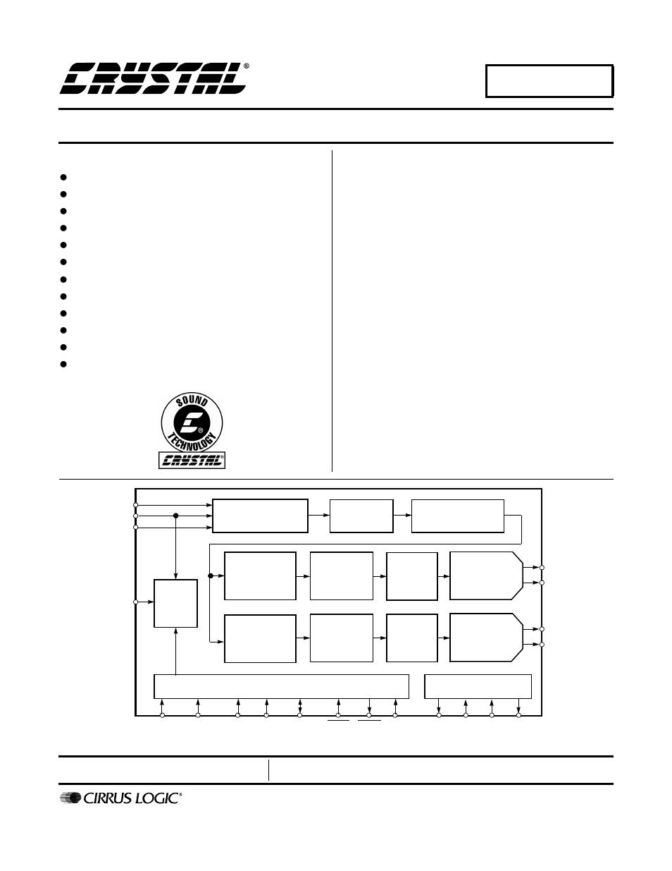
Table of contents
Document Outline
- CS43122
- Features
- Description
- Table of Contents
- List of Figures
- List of Tables
- 1. Characteristics/Specifications
- 2. Typical Connection Diagram
- 3. Register Description
- 4. Pin Description
- 5. Applications
- 6. Control Port Interface
- 6.1 SPI Mode
- 6.2 2 Wire Mode
- 6.3 Memory Address Pointer (MAP)
- Table 4. Operational Mode 0 (16 to 55 kHz) Digital Interface Format Options
- Table 5. Operational Mode 0 (16 to 55 kHz) De-Emphasis Options
- Table 6. Operational Mode 1 (45 to 105 kHz) Sample Rate Mode Options
- Table 7. Operational Mode 2 (95 to 200 kHz) Sample Rate Mode Options
- Figure 7. Operational Mode 0 Transition Band
- Figure 8. Operational Mode 0 Stopband Rejection
- Figure 9. Operational Mode 0 Transition Band
- Figure 10. Operational Mode 0 Frequency Response
- Figure 11. Operational Mode 0 Stopband
- Figure 12. Operational Mode 0 Transition Band
- Figure 13. Operational Mode 0 Transition Band
- Figure 14. Operational Mode 0 Frequency Response
- Figure 15. Operational Mode 2 Stopband Rejection
- Figure 16. Operational Mode 2 Transition Band
- Figure 17. Operational Mode 2 Transition Band
- Figure 18. Operational Mode 2 Frequency Response
- Figure 19. De-Emphasis Curve
- Figure 20. Format 0, Left Justified
- Figure 21. Format 1, I2S
- Figure 22. Format 2, Right Justified, 16-Bit Data
- Figure 23. Format 3, Right Justified, 24-Bit Data
- 7. Parameter Definitions
- 8. References
- 9. Package Dimensions