Analog characteristics – Cirrus Logic CS43122 User Manual
Page 7
CS43122
7
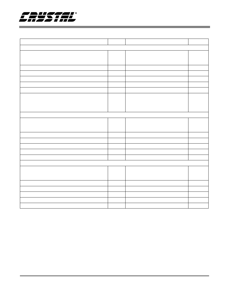
ANALOG CHARACTERISTICS
(Continued)
Notes:
4. Response is clock dependent and will scale with Fs. Note that the response plots (Figures 7-18) have
been normalized to Fs and can be de-normalized by multiplying the X-axis scale by Fs.
5. For Operational Mode 0, the Measurement Bandwidth is 0.5465 Fs to 1.4 Fs.
For Operational Mode 1, the Measurement Bandwidth is 0.570 Fs to 1.4 Fs.
For Operational Mode 2, the Measurement Bandwidth is 0.635 Fs to 1.3 Fs.
6. Group Delay for Fs=48 kHz 37/48 kHz=770
µ
s
7. De-emphasis is available only in Operational Mode 0.
Parameter
Symbol
Min
Typ
Max
Unit
Combined Digital and On-chip Analog Filter Response - Operational Mode 0
Passband
(Note 4)
to -0.1 dB corner
to -3 dB corner
-
-
-
-
0.470
0.492
Fs
Fs
Frequency Response 10 Hz to 20 kHz
-.020
-
+0.015
dB
Passband Ripple
-
-
±0.0001
dB
StopBand
.5465
-
-
Fs
StopBand Attenuation
(Note 5)
102
-
-
dB
Group Delay
(Note 6)
tgd
-
37/Fs
-
s
De-emphasis Error
(Note 7)
Fs = 32 kHz
(Relative to 1 kHz)
Fs = 44.1 kHz
Fs = 48 kHz
-
-
-
-
-
-
±0.10
±0.10
±0.13
dB
dB
dB
Combined Digital and On-chip Analog Filter Response - Operational Mode 1
Passband
(Note 4)
to -0.1 dB corner
to -3 dB corner
0
0
-
-
0.448
0.486
Fs
Fs
Frequency Response 10 Hz to 20 kHz
-0.017
-
0.035
dB
Passband Ripple
-
-
±0.0008
dB
StopBand
.570
-
-
Fs
StopBand Attenuation
(Note 5)
82
-
-
dB
Group Delay
tgd
-
20/Fs
-
s
Combined Digital and On-chip Analog Filter Response - Operational Mode 2
Passband
(Note 4)
to -0.1 dB corner
to -3 dB corner
-
-
-
-
0.385
0.472
Fs
Fs
Frequency Response 10 Hz to 20 kHz
0
-
+0.015
dB
Passband Ripple
-
-
±0.00065
dB
StopBand
0.635
-
-
Fs
StopBand Attenuation
(Note 5)
83
-
-
dB
Group Delay
tgd
-
11/Fs
-
s