2 output connections, Figure 18. cs4270 recommended analog output filter, 6 mute control – Cirrus Logic CS4270 User Manual
Page 27: Figure 19. suggested active-low mute circuit, Cs4270
DS686F1
27
CS4270
5.5.2
Output Connections
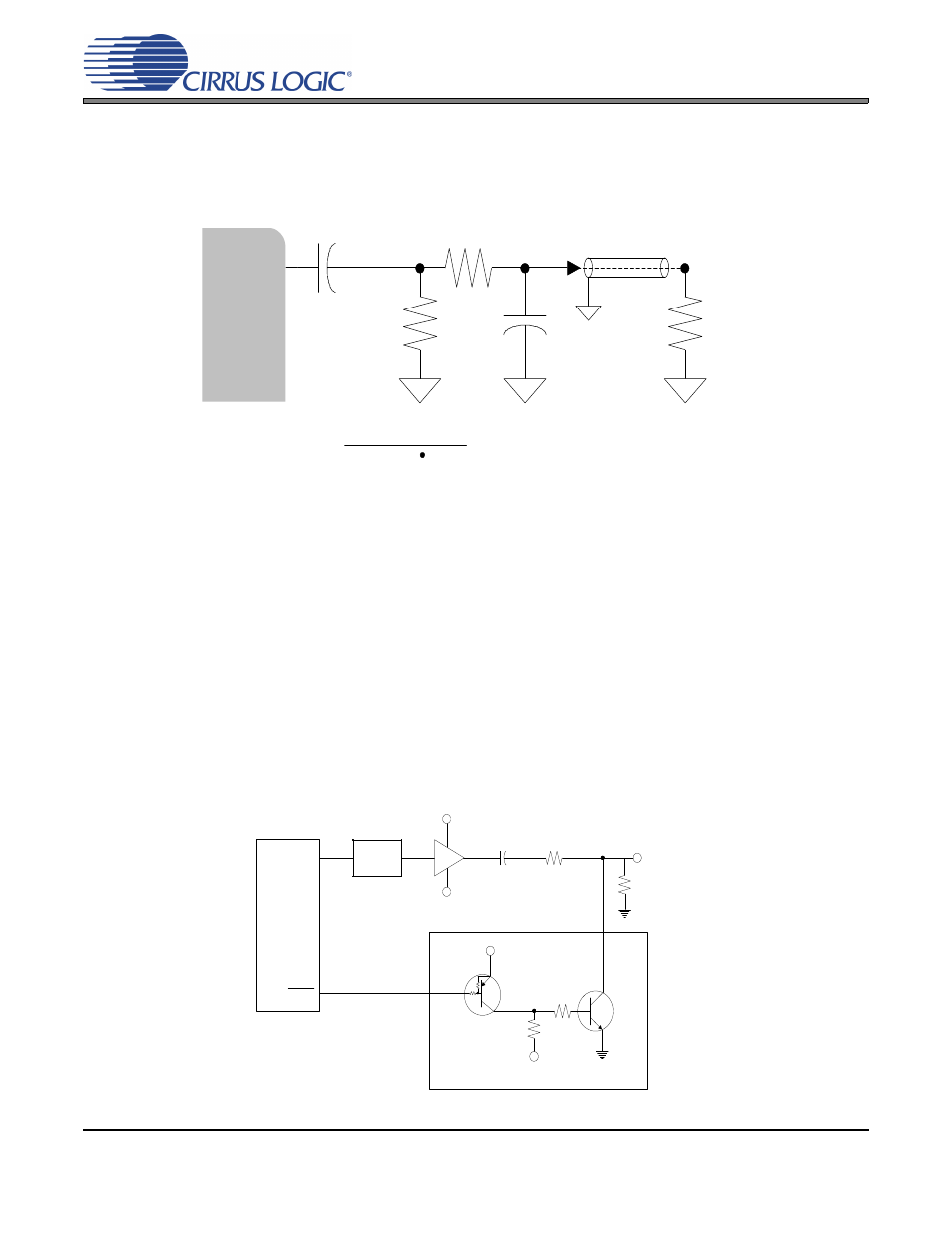
The analog output filter present in the CS4270 is a switched-capacitor low pass filter. Its response, com-
bined with that of the digital interpolator, is given in
. The recommended external analog
circuitry is shown in
.
5.6
Mute Control
The Mute Control pins become active during power-up initialization, reset, muting, when the MCLK to LRCK
ratio is incorrect, and during power-down. The MUTE pins are intended to be used as control for an external
mute circuit in order to add device mute capability.
The CS4270 also features Auto-Mute, which is enabled by default. The Auto-Mute function causes the
MUTE pin corresponding to an individual channel to activate following the reception of 8192 consecutive
static-level audio samples on the respective channel. A single transition of data on the channel will cause
the corresponding MUTE pin to deactivate.
Use of the Mute Control function is not mandatory but recommended for designs requiring the absolute min-
imum in extraneous clicks and pops. Also, use of the Mute Control function can enable the system designer
to achieve idle channel noise/signal-to-noise ratios which are only limited by the external mute circuit. The
MUTE pins are active-low. See
for a suggested active-low mute circuit.
Figure 18. CS4270 Recommended Analog Output Filter
Analog Output
R
+ 470
C =
4Fs (R
470 )
3.3 µF
10 k
C
470
+
R
ext
ext
ext
AOUTx
CS4270
LPF
+V
-V
560
Audio
Out
2 k
10 k
-V
+V
A
MMUN2111LT1
AOUTx
CS4270
AC
Couple
47 k
MUTEx
Figure 19. Suggested Active-Low Mute Circuit