Cirrus Logic CS4270 User Manual
Bit, 192-khz stereo audio codec, Cs4270, D/a features
Copyright
Cirrus Logic, Inc. 2010
(All Rights Reserved)
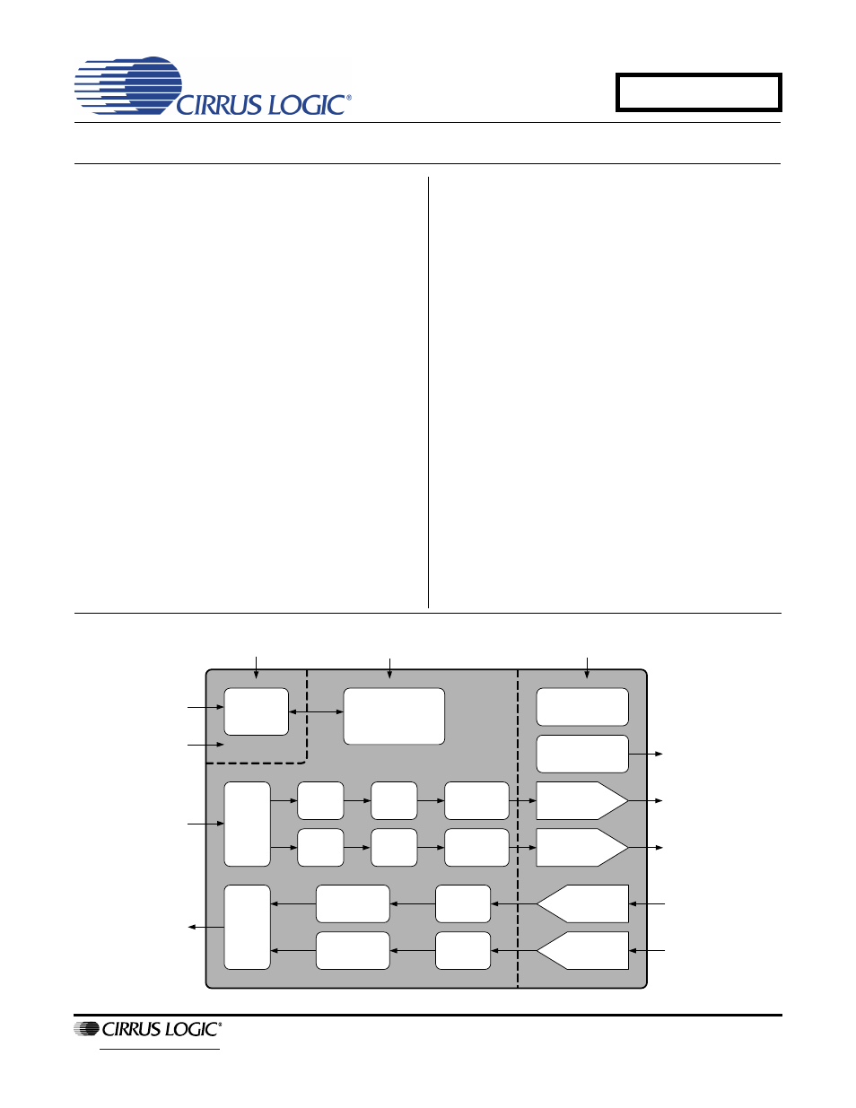
24-Bit, 192-kHz Stereo Audio CODEC
D/A Features
High Performance
– 105 dB Dynamic Range
– -87 dB THD+N
Selectable Serial Audio Interface Formats
– Left-Justified up to 24 bits
– I²S up to 24 bits
– Right-Justified 16, and 24 bits
Control Output for External Muting
Digital De-Emphasis
Popguard
®
Technology
Multi-bit
Conversion
Digital Volume Control
Single-Ended Output
A/D Features
High Performance
– 105 dB Dynamic Range
– -95 dB THD+N
Multi-bit
Conversion
High-Pass Filter to Remove DC Offsets
Selectable Serial Audio Interface Formats
– Left-Justified up to 24 bits
– I²S up to 24 bits
Single-Ended Input
System Features
Direct Interface with Logic Levels 1.8 V to 5 V
Internal Digital Loopback
Stand-Alone or Serial Control Port Functionality
Single-Ended Analog Architecture
Supports all Audio Sample Rates from 4 kHz to
216 kHz
3.3- or 5-V Core Supply
Internal Voltage
Reference
Software or
Stand-Alone
Configuration
Analog Out A
(Left)
PCM Serial
Audio Input
Volume
Control
ADC
Digital
Filter
Multi-bit
Modulator
External Mute
Control
Mute Signals
PCM Serial
Audio Output
Configuration
Registers
Serial
Audio
Input
Level
Translators
Volume
Control
Serial
Audio
Output
High Pass
Filter
High Pass
Filter
Multi-bit
Modulator
ADC
Digital
Filter
Switch-Cap
DAC and
Analog Filter
Switch-Cap
DAC and
Analog Filter
____
RST
VLC
1.8 V to 5 V
Switch-Cap
ADC
Switch-Cap
ADC
DAC
Digital
Filter
DAC
Digital
Filter
VD
3.3 V to 5 V
VA
3.3 V to 5 V
Analog Out B
(Right)
Analog Input A
(Left)
Analog Input B
(Right)
AUGUST '10
DS686F1
CS4270
Document Outline
- 1. Pin Descriptions
- 2. Digital I/O Pin Characteristics
- 3. Typical Connection Diagram
- 4. Characteristics and Specifications
- Specified Operating Conditions
- Absolute Maximum Ratings
- DAC Analog Characteristics
- DAC Combined Interpolation & Analog FIlter Response
- ADC Analog Characteristics
- ADC Digital Filter CharacteristicS
- DC Electrical Characteristics
- Digital SWITCHING Characteristics
- Switching Characteristics - Serial Audio Interface
- Figure 4. Master Mode, Left-Justified SAI
- Figure 5. Slave Mode, Left-Justified SAI
- Figure 6. Master Mode, I·S SAI
- Figure 7. Slave Mode, I·S SAI
- Figure 8. Master and Slave Mode, SCLK/SDIN
- Figure 9. Format 0, Left-Justified up to 24-Bit Data
- Figure 10. Format 1, I·S up to 24-Bit Data
- Figure 11. Format 2 or 3, Right-Justified 16-Bit or 24-Bit Data (Serial Control Port Mode Only)
- Switching Characteristics - Software Mode - I·C Format
- Switching Characteristics - Software Mode - SPI Format
- 5. Applications
- 5.1 Stand-Alone Mode
- 5.2 Serial Control Port Mode
- 5.3 Popguard Transient Control
- 5.4 De-Emphasis Filter (Single-Speed Mode Only)
- 5.5 Analog Connections
- 5.6 Mute Control
- 5.7 Synchronization of Multiple Devices
- 5.8 Grounding and Power Supply Decoupling
- 6. Software Mode
- 7. Register Quick Reference
- 8. Register Description
- 9. Filter Plots
- Figure 23. DAC Single-Speed Stopband Rejection
- Figure 24. DAC Single-Speed Transition Band
- Figure 25. DAC Single-Speed Transition Band (detail)
- Figure 26. DAC Single-Speed Passband Ripple
- Figure 27. DAC Double-Speed Stopband Rejection
- Figure 28. DAC Double-Speed Transition Band
- Figure 29. DAC Double-Speed Transition Band (detail)
- Figure 30. DAC Double-Speed Passband Ripple
- Figure 31. DAC Quad-Speed Stopband Rejection
- Figure 32. DAC Quad-Speed Transition Band
- Figure 33. DAC Quad-Speed Transition Band (detail)
- Figure 34. DAC Quad-Speed Passband Ripple
- Figure 35. ADC Single-Speed Stopband Rejection
- Figure 36. ADC Single-Speed Stopband (detail)
- Figure 37. ADC Single-Speed Transition Band (detail)
- Figure 38. ADC Single-Speed Passband Ripple
- Figure 39. ADC Double-Speed Stopband Rejection
- Figure 40. ADC Double-Speed Stopband (detail)
- Figure 41. ADC Double-Speed Transition Band (detail)
- Figure 42. ADC Double-Speed Passband Ripple
- Figure 43. ADC Quad-Speed Stopband Rejection
- Figure 44. ADC Quad-Speed Stopband (detail)
- Figure 45. ADC Quad-Speed Transition Band (detail)
- Figure 46. ADC Quad-Speed Passband Ripple
- 10. Parameter Definitions
- 11. Package Dimensions
- 12. Ordering Information
- 13. Revision History