1 auto-increment control (incr), 2 register pointer (map), Figure 6. control port timing, spi mode – Cirrus Logic CS4221 User Manual
Page 24: Figure 7. control port timing, i2c mode, 9 memory address pointer (map), Control port timing, i
CS4220 CS4221
24
DS284PP3
8.9
Memory Address Pointer (MAP)
8.9.1
AUTO-INCREMENT CONTROL (INCR)
Default = 0
0 - Disabled
1 - Enabled
8.9.2
REGISTER POINTER (MAP)
Default = 000
7
6
5
4
3
2
1
0
INCR
Reserved
Reserved
Reserved
Reserved
MAP2
MAP1
MAP0
0
0
0
0
0
0
0
0
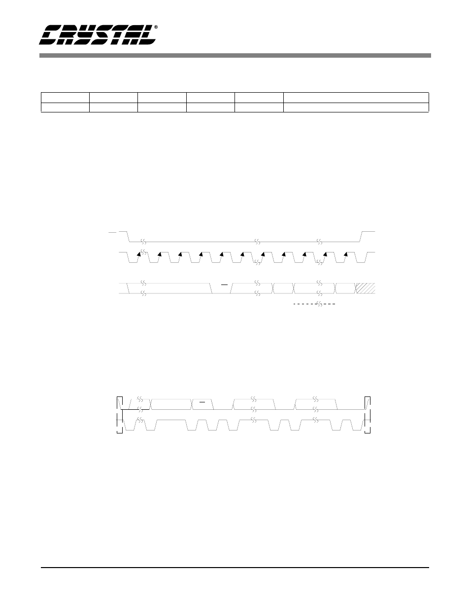
CS
CCLK
CDIN
CHIP
ADDRESS
0010000
R/W
MAP
DATA
MSB
LSB
byte 1
byte n
MAP = Memory Address Pointer
Figure 6. Control Port Timing, SPI mode
SDA
SCL
001000
ADDR
AD0
R/W
ACK
DATA 1-8
ACK
DATA 1-8
ACK
Start
Stop
Figure 7. Control Port Timing, I
2
C mode
This manual is related to the following products: