Typical connection diagram — cs4220, Figure 4. cs4220 recommended connection diagram, Cs4220 – Cirrus Logic CS4221 User Manual
Page 10
CS4220 CS4221
10
DS284PP3
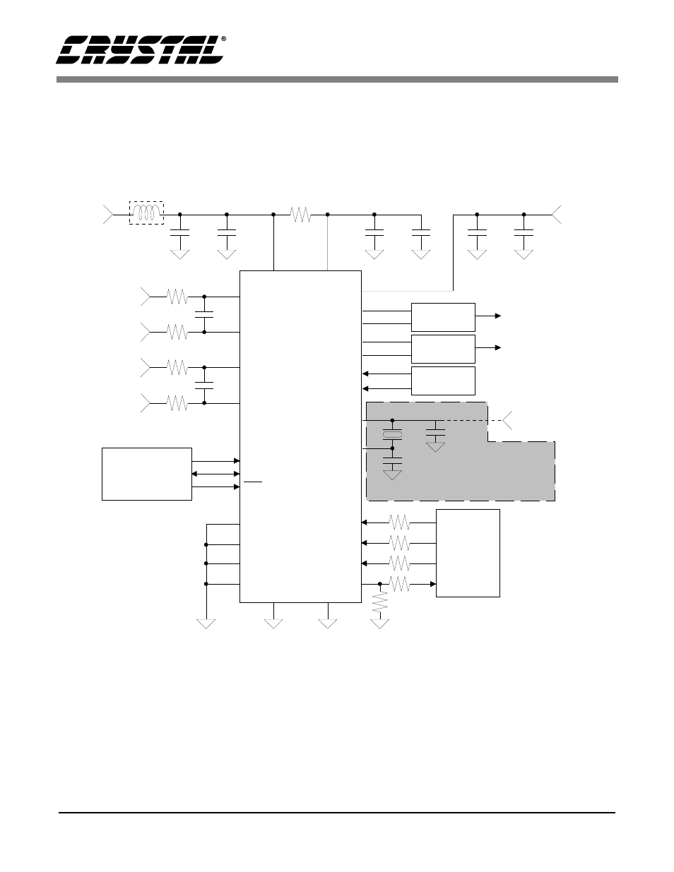
2. TYPICAL CONNECTION DIAGRAM — CS4220
AINL+
AINL-
1 µF
+
0.1 µF
2
Ω
0.1 µF + 1 µF
+5V
Supply
21
6
VA
VD
Ferrite Bead
2.2 nF
150
Ω
150
Ω
AINR+
AINR-
2.2 nF
150
Ω
150
Ω
20
19
17
16
22
7
AGND
DGND
10
11
Mode Selection
DIF1
DIF0
5
4
Audio
DSP
SCLK
LRCK
9
SDIN
8
SDOUT
R
s
R
s
CS4220
27
RST
R
= 500
Ω
NC
1
NC
14
NC
15
NC
28
R
s
R
s
s
0.1 µF + 1 µF
13
VL
+2.7 - 5V
47 k
Ω
*
* Required for
Master Mode only
Digital Audio
Source
18
25
26
AOUTL+
AOUTL-
24
23
Analog Filter
AOUTR+
AOUTR-
12
DEM0
DEM1
XTI
XTO
2
3
External
Clock Input
40 pF
40 pF
Eliminate the crystal
and capacitors when
using an external
clock input
Analog Filter
Figure 4. CS4220 Recommended Connection Diagram
(Also see
Recommended Layout Diagram)
This manual is related to the following products: