Cirrus Logic CS4221 User Manual
Bit stereo audio codec with 3v interface, Preliminary product information, Features
Preliminary Product Information
This document contains information for a new product.
Cirrus Logic reserves the right to modify this product without notice.
1
Copyright
Cirrus Logic, Inc. 1999
(All Rights Reserved)
P.O. Box 17847, Austin, Texas 78760
(512) 445 7222 FAX: (512) 445 7581
http://www.cirrus.com
24-Bit Stereo Audio Codec with 3V Interface
Features
l
100 dB Dynamic Range A/D Converters
l
100 dB Dynamic Range D/A Converters
l
105 dB DAC Signal-to-Noise Ratio (EIAJ)
l
Analog Volume Control (CS4221 only)
l
Differential Inputs / Outputs
l
On-chip Anti-aliasing and Output Smoothing
Filters
l
De-emphasis for 32, 44.1 and 48 kHz
l
Supports Master and Slave Modes
l
Single +5 V power supply
l
On-Chip Crystal Oscillator
l
3 - 5 V Digital Interface
Description
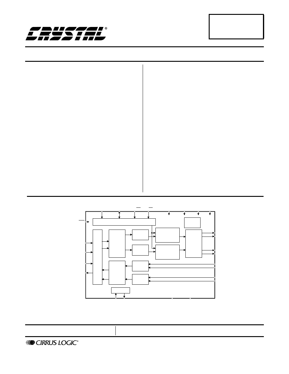
The CS4220/1 is a highly integrated, high performance,
24-bit, audio codec providing stereo analog-to-digital
and stereo digital-to-analog converters using delta-sig-
ma conversion techniques. The device operates from a
single +5 V power supply, and features low power con-
sumption. Selectable de-emphasis filter for 32, 44.1, and
48 kHz sample rates is also included.
The CS4221 also includes an analog volume control ca-
pable of 113.5 dB attenuation in 0.5 dB steps. The
analog volume control architecture preserves dynamic
range during attenuation. Volume control changes are
implemented using a “soft” ramping or zero crossing
technique.
Applications include digital effects processors, DAT, and
multitrack recorders.
ORDERING INFORMATION
CS4220-KS
-10 to +70 °C
28-pin SSOP
CS4221-KS
-10 to +70 °C
28-pin SSOP
CDB4220/1
Evaluation Board
I
SCL/CCLK SDA/CDIN AD0/CS
MCLK
VD
VA
RST
LRCK
SCLK
SDIN
SDOUT
DGND
AGND
AOUTL+
AOUTL-
AOUTR+
AOUTR-
AINL-
AINL+
AINR-
AINR+
Control Port
Se
ri
a
l
Au
di
o
D
at
a
In
ter
fa
c
e
Digit
a
l
F
ilt
er
s
w
ith
D
e
-E
m
phas
is
D
igit
a
l
F
ilt
ers
Left
DAC
Right
DAC
A
n
alo
g
Lo
w
P
as
s
an
d
O
utp
u
t
S
ta
g
e
Voltage
Reference
Left
ADC
Right
ADC
Volume
Control
(DIF1)
(DIF0)
(DEM0)
I C/SPI
(DEM1)
2
Clock OSC
( ) = CS4220
Volume
Control
V
L
XTI
XTO
*
= CS4221
*
*
APR ‘00
DS284PP3
CS4220
CS4221
Document Outline
- CS4220 CS4221
- Features
- Description
- 1. CHARACTERISTICS and SPECIFICATIONS
- 2. Typical Connection Diagram — CS4220
- 3. Typical Connection Diagram — CS4221
- 4. REGISTER QUICK REFERENCE - CS4221
- 5. REGISTER DESCRIPTIONS - CS4221
- 5.1.1 Power Down ADC (PDN)
- 5.1.2 Left and Right channel High Pass Filter Defeat (HPDR-HPDL)
- 5.1.3 Left and Right Channel ADC Muting (ADMR-ADML)
- 5.1.4 Calibration Control (CAL)
- 5.1.5 Calibration Status (CALP) (Read Only)
- 5.1.6 Clocking Error (CLKE) (Read Only)
- 5.2.1 Mute on Consecutive Zeros (MUTC)
- 5.2.2 Mute Control (MUTR-MUTL)
- 5.2.3 Soft RAMP Control (SOFT)
- 5.2.4 Soft RAMP Step Rate (RMP)
- 5.4.1 Attenuation level (ATT7-ATT0)
- 5.5.1 De-emphasis Control (DEM)
- 5.5.2 Serial Input/Output Data SCLK Polarity Select (DSCK)
- 5.5.3 Serial Data Output Format (DOF)
- 5.5.4 Serial Data Input Format (DIF)
- 5.6.1 Left and Right Channel Acceptance Bit (ACCR-ACCL)
- 5.6.2 Left and Right Channel ADC Output Level (LVR and LVL)
- 5.7.1 Master Clock Control (MCK)
- 6. PIN DESCRIPTIONS — CS4220
- 7. PIN DESCRIPTIONS — CS4221
- 8. APPLICATIONS
- 8.1 Overview
- 8.2 Grounding and Power Supply Decoupling
- 8.3 High Pass Filter
- 8.4 Analog Outputs
- 8.5 Master vs. Slave Mode
- 8.6 De-emphasis
- 8.7 Power-up / Reset / Power Down Calibration
- 8.8 Control Port Interface (CS4221 only)
- 8.8.1 SPI Mode
- 8.8.2 I2C Mode
- 8.9.1 Auto-Increment Control (INCR)
- 8.9.2 Register Pointer (MAP)
- Figure 6. Control Port Timing, SPI mode
- Figure 7. Control Port Timing, I2C mode
- Figure 8. Serial Audio Format 0 (I2S)
- Figure 9. Serial Audio Format 1
- Figure 10. Serial Audio Format 2
- Figure 11. Serial Audio Format 3
- Figure 12. Optional Input Buffer
- Figure 13. Single-ended Input Application
- Figure 14. 2- and 3-Pole Butterworth Filters
- Figure 15. Hybrid Digital/Analog Attenuation
- Figure 16. Hybrid Analog/Digital Attenuation
- 9. ADC/DAC FILTER RESPONSE
- 10. PARAMETER DEFINITIONS
- 11. PACKAGE DIMENSIONS