1 spi interface, 2 usb interface, 3 reset source – Cirrus Logic CRD5376 User Manual
Page 24: 4 clock source, Crd5376
CRD5376
24
DS612RD2
Many connections to the C8051F320 microcontroller are inactive by default, but are provided for conve-
nience during custom reprogramming. Listed below are the default active connections to the microcon-
troller and how they are used.
2.3.2.1
SPI Interface
The microcontroller SPI interface communicates with the CS5376A digital filter to write/read configuration
information from the SPI 1 port and collect conversion data from the SD port. Detailed information about
interfacing to the digital filter SPI 1 and SD ports can be found in the CS5376A data sheet.
2.3.2.2
USB Interface
http://www.silabs.com
).
2.3.2.3
Reset Source
By default, the C8051F320 microcontroller receives its reset signal from the internal power-on reset. This
reset signal is also output to the CS5376A digital filter.
2.3.2.4
Clock Source
By default, the C8051F320 microcontroller uses an internally generated 12 MHz clock for compatibility
with USB standards.
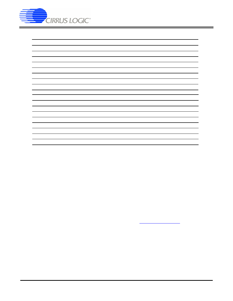
Pin # Pin Name Assignment Description
17
P2.1
TIMEB
Time Break signal to CS5376A
18
P2.0
SYNC
SYNC signal to CS5376A
19
P1.7
BYP_EN
I2C bypass switch control
20
P1.6
SDA_DE
I2C data driver enable
21
P1.5
SCL
I2C clock in/out
22
P1.4
SDA
I2C data in/out
23
P1.3
SSIz
SPI chip select output, active low
24
P1.2
MOSI
SPI master out / slave in
Pin # Pin Name Assignment Assignment
25
P1.1
MISO
SPI master in / slave out
26 P1.0 SCK1 SPI
serial
clock
27
P0.7
Internal VREF bypass capacitors
28
P0.6
SINTz
Serial acknowledge from CS5376A, active low
29 P0.5 RX
UART
receiver
30 P0.4 TX
UART
transmitter
31 P0.3 4.096MHZ
External
clock
input
32
P0.2
SDRDYz
Data ready acknowledge from CS5376A, active low