Cirrus Logic CRD5376 User Manual
Crd5376 multichannel seismic reference design
Copyright
© Cirrus Logic, Inc. 2007
(All Rights Reserved)
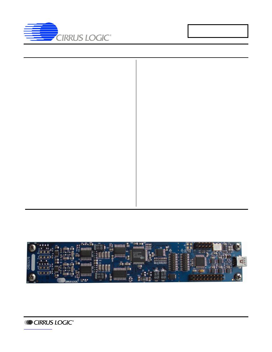
CRD5376
Multichannel Seismic Reference Design
Features
z
Four Channel Seismic Acquisition Node
– CS3301A geophone amplifiers (2x)
– CS3302A hydrophone amplifiers (2x)
– CS5372A dual
∆Σ modulators (2x)
– CS5376A quad digital filter (1x)
– CS4373A
∆Σ test DAC (1x)
– Precision voltage reference
– Clock recovery PLL
z
On-board Microcontroller
– SPI
™
interface to digital filter
– USB communication with PC
z
PC Evaluation Software
– Register setup & control
– FFT frequency analysis
– Time domain analysis
– Noise histogram analysis
General Description
The CRD5376 board is a reference design for the Cirrus
Logic multichannel seismic chip set. Data sheets for the
CS3301A, CS3302A, CS4373A, CS5371A/72A, and
CS5376A devices should be consulted when using the
CRD5376 reference design.
Pin headers connect external differential geophone or
hydrophone sensors to the analog inputs of the mea-
surement channels. An on-board test DAC creates
precision differential analog signals for in-circuit perfor-
mance testing without an external signal source.
The reference design includes an 8051-type microcon-
troller with hardware SPI™ and USB serial interfaces.
The microcontroller communicates with the digital filter
via SPI and with the PC evaluation software via USB.
The PC evaluation software controls register and coeffi-
cient initialization and performs time domain, histogram,
and FFT frequency analysis on captured data.
The CRD5376 features a special breakout connector
used to detach the acquisition and control sections for
remote sensor applications.
ORDERING INFORMATION
CRD5376
Reference Design
NOV ‘07
DS612RD2
Document Outline
- Features & Description
- Table of Contents
- List of Figures
- List of Tables
- 1. Initial Setup
- 2. Hardware Description
- 2.1 Block Diagram
- 2.2 Analog Hardware
- 2.3 Digital Hardware
- 2.4 Power Supplies
- 2.5 PCB Layout
- 3. Software Description
- 4. Bill Of Materials
- 5. Layer Plots
- 6. Schematics