Cirrus Logic CRD5378 User Manual
Crd5378 single-channel seismic reference design
Copyright
© Cirrus Logic, Inc. 2008
(All Rights Reserved)
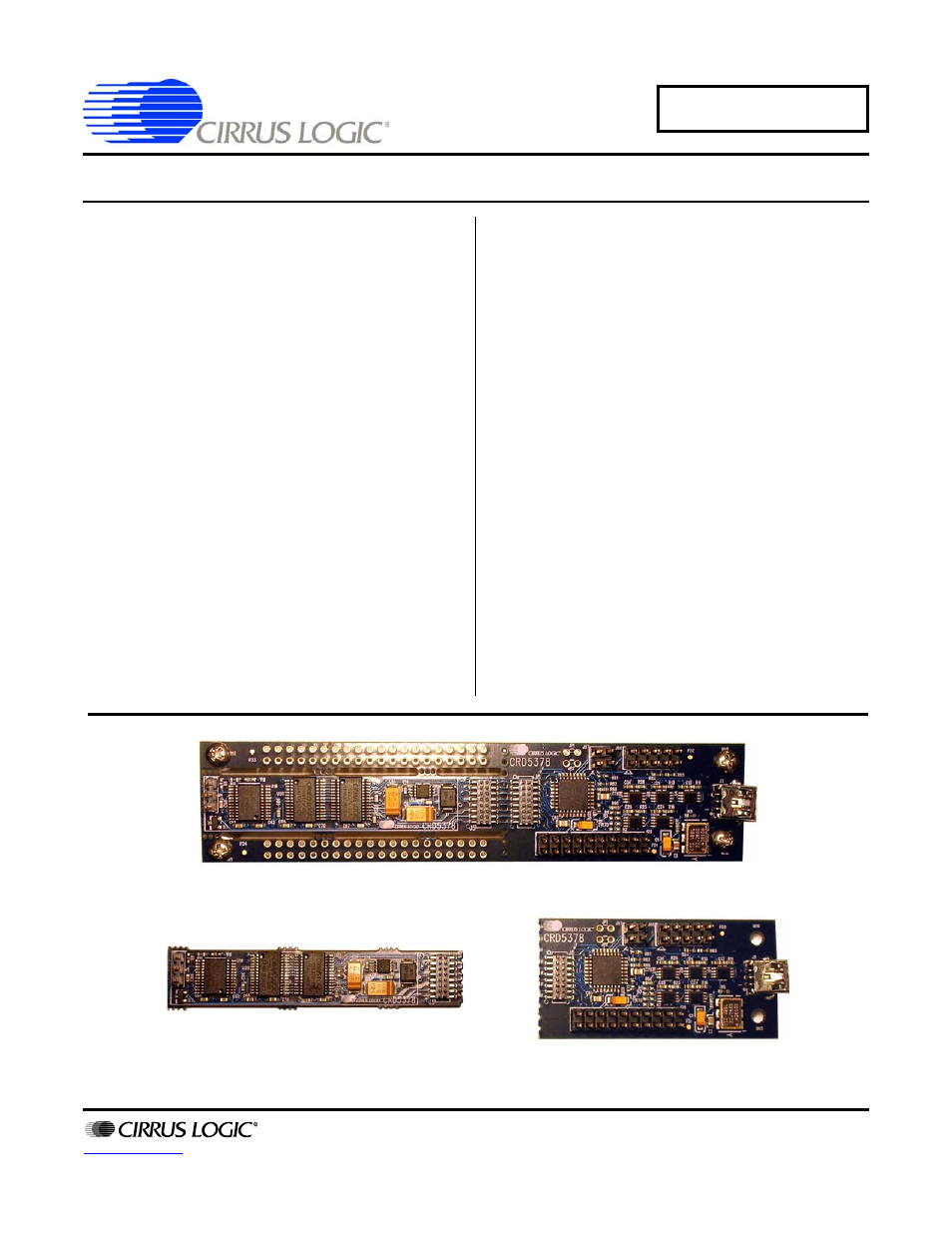
Reference Design Panel (Actual Size)
Data Aquisition Board (Actual Size)
Control Board (Actual Size)
CRD5378
Single-Channel Seismic Reference Design
Features
z
Single-channel Seismic Acquisition Node
– CS3302A hydrophone amplifier
– CS5373A
∆Σ modulator + test DAC
– CS5378 digital filter + PLL
– Precision voltage reference
z
On-board Microcontroller
– SPI
™
interface to digital filter
– USB communication with PC
z
Board Design
– Compact board size: 5” x 1.25” x 0.5”
– Detachable acquisition and telemetry nodes
z
PC Evaluation Software
– Register setup & control
– FFT frequency analysis
– Time domain analysis
– Noise histogram analysis
General Description
The CRD5378 board is a compact reference design for
the Cirrus Logic single-channel seismic chip set. Data
sheets for the CS3302A, CS5373A, and CS5378 devic-
es should be consulted when using the CRD5378
reference design.
Pin headers connect an external differential sensor to
the analog inputs of the measurement channel. An on-
board test DAC creates precision differential analog sig-
nals for in-circuit performance testing without an external
signal source.
The reference design includes an 8051-type microcon-
troller with hardware SPI™ and USB serial interfaces.
The microcontroller communicates with the digital filter
via SPI and with the PC evaluation software via USB.
The PC evaluation software controls register and coeffi-
cient initialization and performs time domain, histogram,
and FFT frequency analysis on captured data.
The CRD5378 board features a special breakout con-
nector used to detach the acquisition and telemetry
sections for remote sensor applications.
ORDERING INFORMATION
CRD5378
Reference Design
JAN ‘08
DS639RD2
Document Outline
- Features & Description
- Revision History
- Table of Contents
- List of Figures
- List of Tables
- 1. Initial Setup
- 2. Hardware Description
- 2.1 Block Diagram
- 2.2 Analog Hardware
- 2.3 Digital Hardware
- 2.4 Power Supplies
- 2.5 PCB Layout
- 3. Software Description
- 4. Bill Of Materials
- 5. Layer Plots
- 6. Schematics