Next Advance SP570-M User Manual
Page 23
NEXT>>>ADVANCE
www.nextadvance.com
SP500 series OEM Programmable Syringe Pump
NE500 series manual
18
Revision 101101
This example demonstrates a Pumping Program whose control depends on an external sensor. Assuming a
pressure sensor that is configured to detect a high pressure point and a low pressure point, the Pumping
Program individually selects whether it will react to the high or low pressure point.
The “Program Output” pin on the TTL I/O connector (pin 5) is used to select the high or low pressure
point. When low, the low pressure point is selected (PHASE 01), and when high, the high pressure point
is selected (PHASE 05). The Program begins by infusing continuously at 10.0 ml/hr (PHASE 02), while a
background trap is set for the low pressure point (PHASE 03). To create a delay when the pressure sensor
is switched from high pressure to low pressure when the “Program Output” pin is set, a small volume is
pumped (PHASE 02, 06) before the background traps are set.
When the low pressure trap is triggered, the pump sets the high pressure trap (PHASE 07) and begins to
increment the flow rate. The flow rate is incremented in 1.0 ml/hr steps with every 0.25 ml dispensed
(PHASE 08-10). If the high pressure trap hasn’t as yet been triggered, the flow rate will max out at 25.0
ml/hr while waiting for the high pressure trap (PHASE 11). When the high pressure point is reached, the
pump immediately will drop down to 10.0 ml/hr (PHASE 02), and once again wait for the low pressure
point.
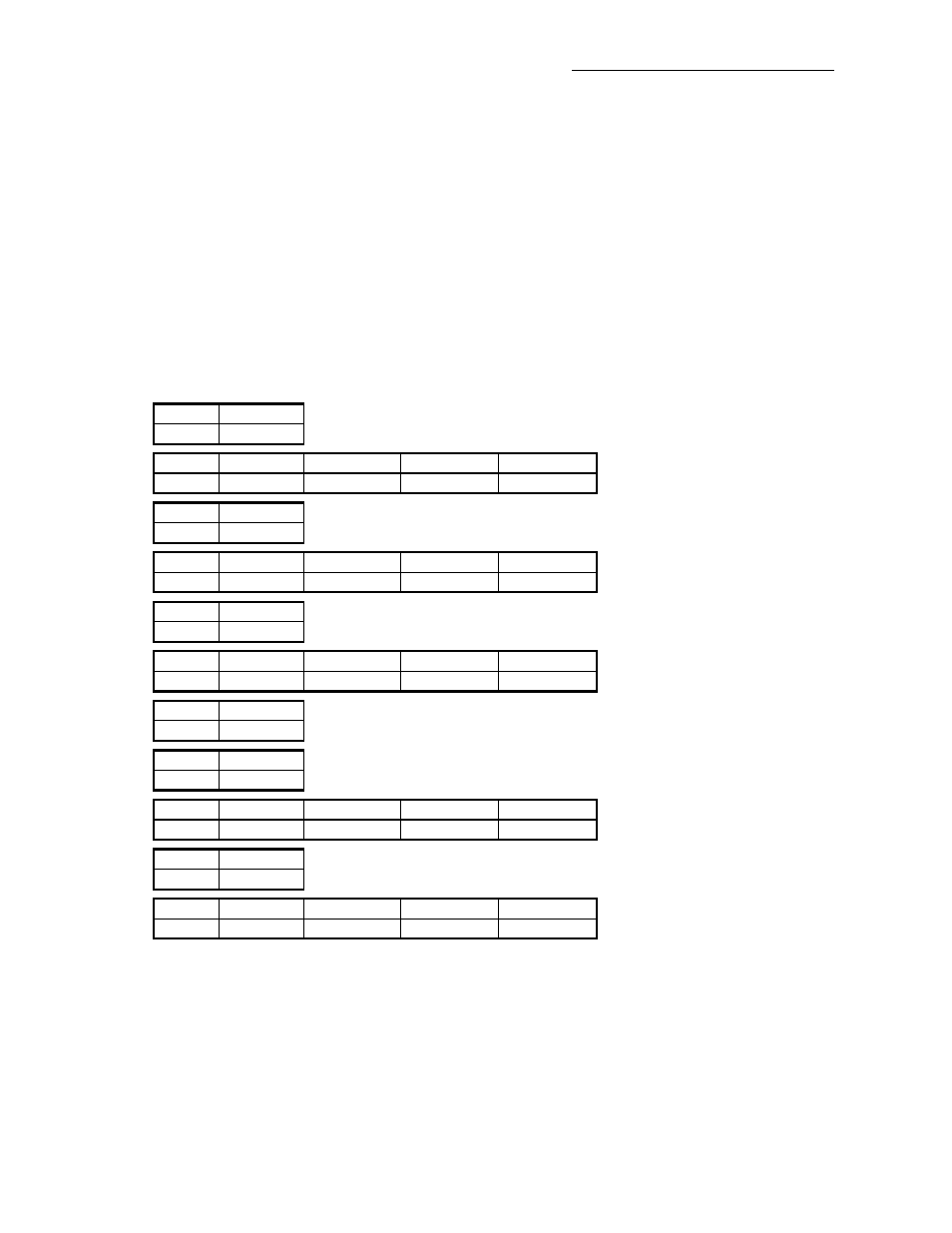
Phase
Function
1
OUT 0
Phase
Function
Rate
Volume
Direction
2
RAT
10.0 ml/hr
0.005
Infuse
Phase
Function
3
EVN 05
Phase
Function
Rate
Volume
Direction
4
RAT
10.0 ml/hr
0.0 ml (off)
Infuse
Phase
Function
5
OUT 1
Phase
Function
Rate
Volume
Direction
6
RAT
10.0 ml/hr
0.005
Infuse
Phase
Function
7
EVN 01
Phase
Function
8
LPS
Phase
Function
Rate
Volume
Direction
9
INC
1.0
0.25 ml
Infuse
Phase
Function
10
L0P 14
Phase
Function
Rate
Volume
Direction
11
RAT
25.0 ml/hr
0.0 ml (off)
Infuse