WIKA 851.02.100 User Manual
Page 8
8
WIKA Operating instructions DELTA-plus, DELTA-comb and DELTA-switch per ATEX
11242370 06/2007 GB/D/F
GB
7. Commissioning
7. Commissioning
7.1 Mounting of the pressure connection
Pressure entries identified j and i
j
high pressure
i
low pressure
During the commissioning process, pressure peaks must be avoided absolutely.
Open the shut-off valves slowly.
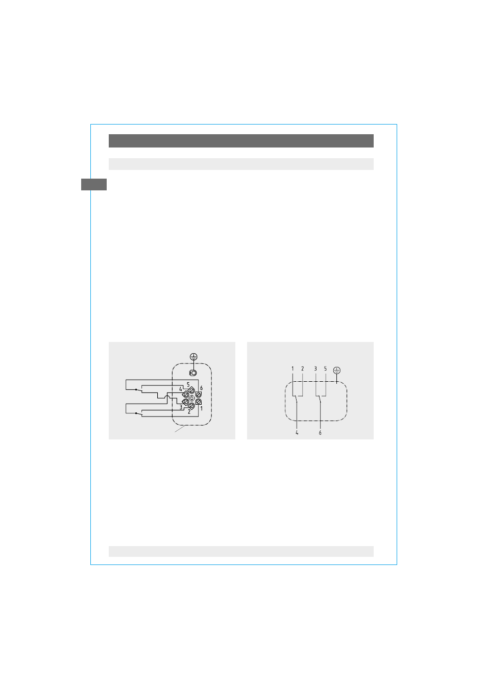
7.2 Wiring details
(applies to Model 702.02/03.100 and 851.02.100)
T
The electrical connections should be made by qualified electricians
T
Connection details and switch functions are given on the instrument rating
plate. Connection terminals (1 ... 6) and the ground terminal are appropriately
marked.
T
The mains connection lines to be provided must be suitable for maximum
instrument power consumption and comply with IEC 227 or IEC 245
T
The instruments must be included in the equipotential bonding of the plant
850.33
2st contact
Connection is via a
terminal box or L-plug
per DIN 43 651
2162679.01
Terminal box
850.33 2nd contact
850.3 1st contact
2162679.0X
850.3
1nd contact
Connection details
Connection is via a
cable gland and cable
Setting the switch point
The switch points are set by means of the setpoint screws, accessible from the
front. The 270 p° assistant scale indicates the current setpoint.
For contact re-adjustment, lever the window out of the case via the recess in its
circumference. The desired switch point can be set by turning the setpoint
screw.
Afterwards press the window back into the case.