WIKA N-11 User Manual
Page 6
2147614.07 GB/D/F/E 04/2009
10 WIKA Operating instructions/Betriebsanleitung/Mode d'emploi/Instrucciones de servicio N-10, N-11
2147614.07 GB/D/F/E 04/2009
11
WIKA Operating instructions/Betriebsanleitung/Mode d'emploi/Instrucciones de servicio N-10, N-11
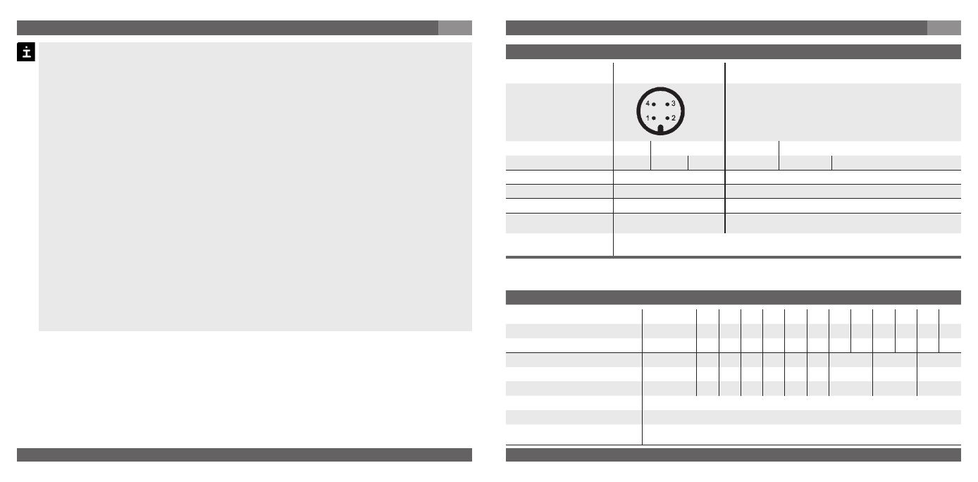
Specifications
Model N-10 / N-11
Pressure ranges
bar
0.1
0.16 0.25 0.4
0.6
1
1.6
2.5
4
6
10
16
Over pressure safety
bar
1
1.5
2
2
4
5
10
10
17
35
35
80
Burst pressure
bar
2
2
2.4
2.4
4.8
6
12
12
20.5 42
42
96
Pressure ranges
bar
25
40
60
100 160 250 400
600
1000
1)
Over pressure safety
bar
50
80
120 200 320 500 800
1200
1500
Burst pressure
bar
96
400 550 800 1000 1200 1700
2)
2400
2)
3000
{Vacuum, gauge pressure, compound range, absolute pressure are available}
1)
Only Model N-10 gültig.
2)
For model N-11: the value specified in the table applies only when sealing is
realised with the sealing ring underneath the hex. Otherwise max. 1500 bar applies.
Electrical connections
Circular connector M12x1
Flying leads with 1.6 m (6 foot) length
2-wire
U+ = 1
U- = 3
U+ = brown U- = green
3-wire
U+ = 1
U- = 3
S+ = 4
U+ = brown U- = green
S+ = white
Cable screen
-
grey
Wire gauge
-
0.5 mm2 (AWG 20)
Diameter of cable
-
6.8 mm
Ingress protection per
IEC 60 529
IP 67
IP 68
The ingress protection classes specified only apply while the pressure transmitter is
connected with female connectors that provide the corresponding ingress protection.
7. Starting, operation
GB
Earth the housing, through the process connection, against electromagnetic fields and
electrostatic discharge.
Operate the pressure transmitter with a shielded cable and earth the shield at least on
one side of the cable, if the cable is longer than 30m (2-wire) or 3m (3-wire), or if it is
run outside of the building.
Ingress protection per IEC 60529 (The ingress protection classes specified only apply
while the pressure transmitter is connected with female connectors that provide the
corresponding ingress protection).
Please observe the following when selecting
the connector:
Temperature range T > T transmitter + 20 K
Ingress protection
≥ IP 54 (explosion protection)
Conductor cross-section
≥ A 0.25 mm
2
the cable:
when selecting the cable length, ensure that it is 3x longer than the cable length
required, so that the cable can be pulled to different locations.
Ensure that the cable diameter you select fits to the cable gland of the connector
Ensure that the cable gland of the mounted connector is positioned correctly and
that the sealings are available and undamaged. Tighten the threaded connection and
check the correct position of the sealings in order to ensure the ingress protection.
Please make sure that the ends of cables with flying leads do not allow any ingress of
moisture.
7. Starting, operation
GB