WIKA IPT-11 User Manual
Page 16
Display
5
6
7
8
4
1
2
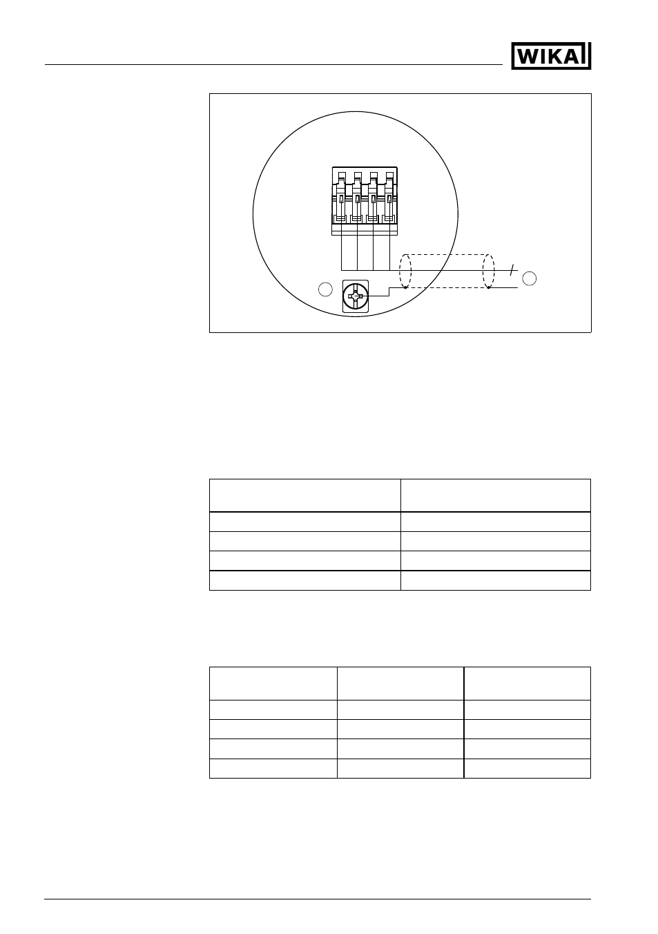
Fig. 9: Wiring plan external indicating and adjustment unit for 4 … 20 mA/HART
sensors
1
To the sensor
2
Grounding on both ends with non-Ex. With Ex, one-sided grounding at the
sensor is recommended, see EN 60079-14.
Connection via cable gland on the sensor
The connection between indicating and adjustment unit and the sensor
is carried out according to the chart:
External indicating and adjustment
unit
Sensor
Terminal 5
Terminal 5
Terminal 6
Terminal 6
Terminal 7
Terminal 7
Terminal 8
Terminal 8
Connection via plug M12 x 1 on the sensor
The connection between indicating and adjustment unit and the sensor
with plug M12 x 1 is carried out according to the chart.
2)
Wire number
External indicating and
adjustment unit
Sensor
1
Terminal 5
PIN
2
2
Terminal 6
PIN
1
3
Terminal 7
PIN
4
4
Terminal 8
PIN
3
2)
Plug M12 x 1, optionally with double chamber housing.
Wiring plan (4 … 20 mA/
HART sensors)
16
External indicating and adjustment unit
5 Connecting to power supply
31550
-EN
-100726