Specifications model il-10, Wire – WIKA IL-10 User Manual
Page 6
2146455.08 GB/D/F/E 08/2009
10 WIKA Operating instructions/Betriebsanleitung/Mode d'emploi/Instrucciones de servicio IL-10
2146455.08 GB/D/F/E 08/2009
11
WIKA Operating instructions/Betriebsanleitung/Mode d'emploi/Instrucciones de servicio IL-10
Specifications
Model IL-10
Pressure ranges
bar
0.1
0.16
0.25
0.4
0.6
1
Over pressure safety
bar
1
1.5
2
2
4
5
Burst pressure
bar
2
2
2.4
2.4
4.8
6
Pressure ranges
bar
1.6
2.5
4
6
10
16
25
Over pressure safety
bar
10
10
17
35
35
35
35
Burst pressure
bar
12
12
20.5
42
42
42
42
Materials
Wetted parts
Cable
»
PUR {FEP up to 10 bar}
Protection cap
»
Stainless steel {Hastelloy}
Case
Stainless steel {Hastelloy}
Internal transmission fluid
Synthetic oil
Power supply U
B
U
B
in VDC
10 <
U
B
≤
30
Signal output and
4 … 20 mA, 2-wire
maximum ohmic load R
A
R
A
in Ohm
R
A
≤ (U
B
– 10 V) / 0.02 A - (length of flying leads in m x 0.14 Ohm)
Insulation voltage
Insulation complies with EN 50020, 6.4, 12
Accuracy
% of span
≤
0.25
{0.125}
1)
(BFSL)
≤
0.5
2)
{0.25}
1) 2)
1)
Accuracy { } for pressure ranges
≥ 0.25 bar
2)
Including non-linearity, hysteresis, zero point and full scale error (corresponds to
error of measurement per IEC 61298-2).
Adjusted in vertical mounting position with lower pressure connection.
Non-linearity
% of span
≤
0.2
(BFSL) according to IEC 61298-2
Non-repeatability
% of span
≤
0.1
1-year stability
% of span
≤
0.2
(at reference conditions)
Permissible temperature of
Medium
3) 4) 5)
-10 ... +60 °C
-14 ... +140 °F
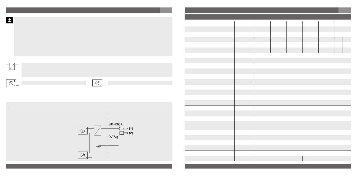
Load (e.g. display)
Power supply
UB+/Sig+
Positive supply / measurement connection
OV/Sig-
Negative supply / measurement connection
Flying leads, conducter cross
section up
to max. 0.25 mm ²/AWG 24 with
end splices, conducter outer
diameter 7.5 mm,
IP 68 (Please note "Over pressure
safety" in Chapter 7 Specification)
brown
green
7. Starting, operation
GB
Operate the level probe with a shielded cable and earth the shield at least on one
side of the cable, if the cable is longer than 30m (2-wire), or if it is run outside of the
building.
There mus be no differences in potential between medium/tank and the grounding of
the junction box and the control cabinet when the shield of the cable is applied.
Ingress protection per IEC 60529
Please make sure that the ends of cables with flying leads do not allow any ingress of
moisture.
With a line transformer you realise the mandatory galvanic isolation of the voltage
and current supply between hazardous and non-hazardous areas and ensure the
safety connection data.
Non hazardous
area
Hazardous
(classified) area
Screen/case, grey
7. Starting, operation
GB
-wire